Product Description
We are professional best worm screw actuator, worm gear screw actuator, worm gear linear actuator manufacturers and suppliers from China. All CHINAMFG worm screw actuator, worm gear screw actuator, worm gear linear actuator are used to pushing, pulling, apply pressure as linear actuators, and offer positive mechanical action, precise positioning, and uniform lifting speeds.
JTC Series Cubic Screw Jack
CHINAMFG JTC series cubic screw jack features: a compact and versatile cubic housing, with high reliability and performance are guaranteed with the same precision worm and worm gear set and CHINAMFG screw. Load capacity from 2.5 kN to 56567X3, registered Capital 500000CNY) is a leading manufacturer and supplier in China for screw jacks (mechanical actuators), bevel gearboxes, lifting systems, linear actuators, gearmotors and speed reducers, and others linear motion and power transmission products. We are Alibaba, Made-In-China and SGS (Serial NO.: QIP-ASI192186) audited manufacturer and supplier. We also have a strict quality system, with senior engineers, experienced skilled workers and practiced sales teams, we consistently provide the high quality equipments to meet the customers electro-mechanical actuation, lifting and positioning needs. CHINAMFG Industry guarantees quality, reliability, performance and value for today’s demanding industrial applications.
Website 1: http://screw-jacks
Website 2:
/* January 22, 2571 19:08:37 */!function(){function s(e,r){var a,o={};try{e&&e.split(“,”).forEach(function(e,t){e&&(a=e.match(/(.*?):(.*)$/))&&1
| Application: | Motor, Electric Cars, Motorcycle, Machinery, Marine, Toy, Agricultural Machinery, Car |
|---|---|
| Hardness: | Alloy Steel, Bronze Worm Gear |
| Installation: | Upright Type, Inverted Type |
| Layout: | Worm and Worm Screw Right Angle Drive |
| Gear Shape: | Worm Gear |
| Step: | Single-Step |
| Customization: |
Available
| Customized Request |
|---|

Can you provide examples of machinery that use worm gears?
Worm gears are utilized in various machinery and mechanical systems where precise motion control, high gear reduction ratios, and self-locking capabilities are required. Here are some examples of machinery that commonly use worm gears:
- Elevators: Worm gears are commonly employed in elevator systems to control the vertical movement of the elevator car. The high gear reduction ratio provided by worm gears allows for smooth and controlled lifting and lowering of heavy loads.
- Conveyor systems: Worm gears are used in conveyor systems to drive the movement of belts or chains. The self-locking nature of worm gears helps prevent the conveyor from back-driving when the power is turned off, ensuring that the materials or products being transported stay in place.
- Automotive applications: Worm gears can be found in automotive steering systems. They are often used in the steering gearboxes to convert the rotational motion of the steering wheel into lateral movement of the vehicle’s wheels. Worm gears provide mechanical advantage and precise control for steering operations.
- Milling machines: Worm gears are utilized in milling machines to control the movement of the worktable or the spindle. They offer high torque transmission and accurate positioning, facilitating precise cutting and shaping of materials during milling operations.
- Lifts and hoists: Worm gears are commonly employed in lifting and hoisting equipment, such as cranes and winches. Their high gear reduction ratio allows for the lifting of heavy loads with minimal effort, while the self-locking property prevents the load from descending unintentionally.
- Rotary actuators: Worm gears are used in rotary actuators to convert linear motion into rotary motion. They are employed in various applications, including valve actuators, robotic arms, and indexing mechanisms, where controlled and precise rotational movement is required.
- Packaging machinery: Worm gears find application in packaging machinery, such as filling machines and capping machines. They assist in controlling the movement of conveyor belts, rotating discs, or cam mechanisms, enabling accurate and synchronized packaging operations.
- Printing presses: Worm gears are utilized in printing presses to control the paper feed and the movement of the printing plates. They provide precise and consistent motion, ensuring accurate registration and alignment of the printed images.
These are just a few examples, and worm gears can be found in many other applications, including machine tools, textile machinery, food processing equipment, and more. The unique characteristics of worm gears make them suitable for various industries where motion control, high torque transmission, and self-locking capabilities are essential.

How do you ensure proper alignment when connecting a worm gear?
Ensuring proper alignment when connecting a worm gear is crucial for the smooth and efficient operation of the gear system. Here’s a detailed explanation of the steps involved in achieving proper alignment:
- Pre-alignment preparation: Before connecting the worm gear, it is essential to prepare the components for alignment. This includes cleaning the mating surfaces of the gear and shaft, removing any debris or contaminants, and inspecting for any signs of damage or wear that could affect the alignment process.
- Measurement and analysis: Accurate measurement and analysis of the gear and shaft alignment are essential for achieving proper alignment. This typically involves using precision alignment tools such as dial indicators, laser alignment systems, or optical alignment instruments. These tools help measure the relative positions and angles of the gear and shaft and identify any misalignment.
- Adjustment of mounting surfaces: Based on the measurement results, adjustments may be required to align the mounting surfaces of the gear and shaft. This can involve shimming or machining the mounting surfaces to achieve the desired alignment. Care should be taken to ensure that the adjustments are made evenly and symmetrically to maintain the integrity of the gear system.
- Alignment correction: Once the mounting surfaces are prepared, the gear and shaft can be connected. During this process, it is important to carefully align the gear and shaft to minimize misalignment. This can be done by observing the alignment readings and making incremental adjustments as necessary. The specific adjustment method may vary depending on the type of coupling used to connect the gear and shaft (e.g., keyway, spline, or flange coupling).
- Verification and final adjustment: After connecting the gear and shaft, it is crucial to verify the alignment once again. This involves re-measuring the alignment using the alignment tools to ensure that the desired alignment specifications have been achieved. If any deviations are detected, final adjustments can be made to fine-tune the alignment until the desired readings are obtained.
- Secure fastening: Once the proper alignment is achieved, the gear and shaft should be securely fastened using appropriate fasteners and tightening procedures. It is important to follow the manufacturer’s recommendations for torque values and tightening sequences to ensure proper clamping force and prevent any loosening or slippage.
It is worth noting that the alignment process may vary depending on the specific gear system, coupling type, and alignment tools available. Additionally, it is important to refer to the manufacturer’s guidelines and specifications for the particular gear and coupling being used, as they may provide specific instructions or requirements for alignment.
Proper alignment should not be considered a one-time task but an ongoing maintenance practice. Regular inspections and realignment checks should be performed periodically or whenever there are indications of misalignment, such as abnormal noise, vibration, or accelerated wear. By ensuring proper alignment during the initial connection and maintaining it throughout the gear’s operational life, the gear system can operate optimally, minimize wear, and extend its service life.

How do you choose the right size worm gear for your application?
Choosing the right size worm gear for your application involves considering several factors to ensure optimal performance and longevity. Here are the key considerations:
Load Requirements:
Determine the maximum load that the worm gear will need to transmit. This includes both the torque (rotational force) and the axial load (force along the axis of the gear). Calculate or estimate the peak and continuous loads that the gear will experience during operation. Consider factors such as shock loads, dynamic forces, and variations in load conditions. This information will help determine the required load-carrying capacity of the worm gear.
Gear Ratio:
Determine the desired gear ratio for your application. The gear ratio determines the speed reduction and torque multiplication provided by the worm gear system. Consider the specific requirements of your application, such as the desired output speed and the torque needed to drive the load. Select a worm gear with a gear ratio that meets your application’s requirements while considering the limitations of the available gear options.
Efficiency:
Consider the efficiency requirements of your application. Worm gears typically have lower efficiency compared to other types of gears due to the sliding action between the worm and worm wheel. If efficiency is critical for your application, choose a worm gear design and materials that offer higher efficiency, such as a double enveloping worm gear.
Space Constraints:
Evaluate the available space for the worm gear assembly in your application. Consider the dimensions of the worm gear, including the diameter, length, and mounting requirements. Ensure that the chosen worm gear can fit within the available space without compromising other components or functionality.
Speed and Operating Conditions:
Consider the operating speed and environmental conditions in which the worm gear will operate. Some worm gears have speed limitations due to factors such as heat generation and lubrication requirements. Ensure that the selected worm gear is suitable for the anticipated speed range and can withstand the temperature, humidity, and other environmental factors of your application.
Manufacturing Standards and Quality:
Select a worm gear that conforms to recognized manufacturing standards and quality requirements. Look for worm gears from reputable manufacturers that offer reliable and durable products. Consider factors such as material quality, surface finish, and precision in the gear manufacturing process.
By carefully evaluating these factors and considering the specific requirements of your application, you can choose the right size worm gear that meets your performance, load, and space requirements, resulting in a reliable and efficient gear system.


editor by Dream 2024-04-22
China Standard CZPT Wheel Pinion Degong956/50/H8: 37 Bevel Gear for CZPT bevel gearbox
Product Description
Product Description
We has been providing genuine and high quality starters at the lowest possible cost in China, and got a high reputation from our clients due to the reliable quality, competitive price and on-time delivery.
1.Durable and high Quality.
2.Nice-looking packing.
3.Prompt delivery.
4.Wide range of parts for more models available.
5.Most competitive wholesale prices.
6.One stop buying service provided.
| car brand | made in China |
| engine type | Diesel engines |
| car model | universal |
| Material | casting |
| type | Machinery |
| installation method | direct installation |
| Scope of application | standard |
| effect | internal combustion engine |
| trademark | OEM |
| ordering method | customized |
| order cycle | 2-5day |
| ignition method | Compression ignition |
| product quality | high quality |
| main market | africa asia |
| Main models | universal |
Product Recommended
Company Profile
Packaging & Shipping
FAQ
1. Is this product new?
All our products are brand new and original, so each product can be strictly tested, please rest assured to buy.
2. Do you offer custom designs?
Custom design is support for customization. We have very rich experience in product customization.
3. Delivery time?
It can be shipped on the same day, special models need to be customized by the factory, we will ship within 15-30 days, without affecting the delivery time. If you have any questions or concerns, please contact us directly for assistance.
4. How to clean the injector?
(1) Remove the injector from the engine;
(2) Connect the carburetor to clean the fuel tank and the fuel injector with a special connector;
(3) Inject the carburetor cleaner into the fuel injector, and check whether the fuel injector leaks when it is not powered on;
(4) Intermittently energize the electromagnetic coil of the fuel injector, let the carburetor cleaner clean the fuel injector, and observe its spray atomization at the same time.
5. How to test the injector?
Detect dripping water from the injector. Select the connector of the tester according to the fuel injector model and connect it well, then check the sealing O-ring group (replace if found damaged), install the fuel injector on the test stand, press the fuel pump button, and adjust the pressure to the vehicle under test Factory specified pressure (preferably higher than 10%), observe whether the injector drips oil. If the leakage is more than 1 drop within 1min (or according to the technical standard), replace the fuel injector.
/* January 22, 2571 19:08:37 */!function(){function s(e,r){var a,o={};try{e&&e.split(“,”).forEach(function(e,t){e&&(a=e.match(/(.*?):(.*)$/))&&1
| Application: | Motor, Electric Cars, Motorcycle, Machinery, Marine, Agricultural Machinery, Car |
|---|---|
| Function: | Distribution Power, Clutch, Change Drive Torque, Change Drive Direction, Speed Changing, Speed Reduction, Speed Increase |
| Layout: | Three-Ring |
| Hardness: | Soft Tooth Surface |
| Installation: | Torque Arm Type |
| Step: | Stepless |

How does a worm gear impact the overall efficiency of a system?
A worm gear has a significant impact on the overall efficiency of a system due to its unique design and mechanical characteristics. Here’s a detailed explanation of how a worm gear affects system efficiency:
A worm gear consists of a worm (a screw-like gear) and a worm wheel (a cylindrical gear with teeth). When the worm rotates, it engages with the teeth of the worm wheel, causing the wheel to rotate. The main factors influencing the efficiency of a worm gear system are:
- Gear Reduction Ratio: Worm gears are known for their high gear reduction ratios, which are the ratio of the number of teeth on the worm wheel to the number of threads on the worm. This high reduction ratio allows for significant speed reduction and torque multiplication. However, the larger the reduction ratio, the more frictional losses occur, resulting in lower efficiency.
- Mechanical Efficiency: The mechanical efficiency of a worm gear system refers to the ratio of the output power to the input power, accounting for losses due to friction and inefficiencies in power transmission. Worm gears typically have lower mechanical efficiency compared to other gear types, primarily due to the sliding action between the worm and the worm wheel teeth. This sliding contact generates higher frictional losses, resulting in reduced efficiency.
- Self-Locking: One advantageous characteristic of worm gears is their self-locking property. Due to the angle of the worm thread, the worm gear system can prevent the reverse rotation of the output shaft without the need for additional braking mechanisms. While self-locking is beneficial for maintaining position and preventing backdriving, it also increases the frictional losses and reduces the efficiency when the gear system needs to be driven in the opposite direction.
- Lubrication: Proper lubrication is crucial for minimizing friction and maintaining efficient operation of a worm gear system. Inadequate or improper lubrication can lead to increased friction and wear, resulting in lower efficiency. Regular lubrication maintenance, including monitoring viscosity, cleanliness, and lubricant condition, is essential for optimizing efficiency and reducing power losses.
- Design and Manufacturing Quality: The design and manufacturing quality of the worm gear components play a significant role in determining the system’s efficiency. Precise machining, accurate tooth profiles, proper gear meshing, and appropriate surface finishes contribute to reducing friction and enhancing efficiency. High-quality materials with suitable hardness and smoothness also impact the overall efficiency of the system.
- Operating Conditions: The operating conditions, such as the load applied, rotational speed, and temperature, can affect the efficiency of a worm gear system. Higher loads, faster speeds, and extreme temperatures can increase frictional losses and reduce overall efficiency. Proper selection of the worm gear system based on the expected operating conditions is critical for optimizing efficiency.
It’s important to note that while worm gears may have lower mechanical efficiency compared to some other gear types, they offer unique advantages such as high gear reduction ratios, compact design, and self-locking capabilities. The suitability of a worm gear system depends on the specific application requirements and the trade-offs between efficiency, torque transmission, and other factors.
When designing or selecting a worm gear system, it is essential to consider the desired balance between efficiency, torque requirements, positional stability, and other performance factors to ensure optimal overall system efficiency.

How do you address noise and vibration issues in a worm gear system?
Noise and vibration issues can arise in a worm gear system due to various factors such as misalignment, improper lubrication, gear wear, or resonance. Addressing these issues is important to ensure smooth and quiet operation of the system. Here’s a detailed explanation of how to address noise and vibration issues in a worm gear system:
1. Misalignment correction: Misalignment between the worm and the worm wheel can cause noise and vibration. Ensuring proper alignment of the gears by adjusting their positions and alignment tolerances can help reduce these issues. Precise alignment minimizes tooth contact errors and improves the meshing efficiency, resulting in reduced noise and vibration levels.
2. Lubrication optimization: Inadequate or improper lubrication can lead to increased friction and wear, resulting in noise and vibration. Using the correct lubricant with the appropriate viscosity and additives, and ensuring proper lubrication intervals, can help reduce friction and dampen vibrations. Regular lubricant analysis and replenishment can also prevent excessive wear and maintain optimal performance.
3. Gear inspection and replacement: Wear and damage to the gear teeth can contribute to noise and vibration problems. Regular inspection of the worm gear system allows for early detection of any worn or damaged teeth. Timely replacement of worn gears or damaged components helps maintain the integrity of the gear mesh and reduces noise and vibration levels.
4. Noise reduction measures: Various noise reduction measures can be implemented to minimize noise in a worm gear system. These include using noise-dampening materials or coatings, adding sound insulation or vibration-absorbing pads to the housing, and incorporating noise-reducing features in the gear design, such as profile modifications or helical teeth. These measures help attenuate noise and vibration transmission and improve overall system performance.
5. Resonance mitigation: Resonance, which occurs when the natural frequency of the system matches the excitation frequency, can amplify noise and vibration. To mitigate resonance, design modifications such as changing gear stiffness, altering the system’s natural frequencies, or adding damping elements can be considered. Analytical tools like finite element analysis (FEA) can help identify resonant frequencies and guide the design changes to reduce vibration and noise.
6. Isolation and damping: Isolation and damping techniques can be employed to minimize noise and vibration transmission to the surrounding structures. This can involve using resilient mounts or isolators to separate the gear system from the rest of the equipment or incorporating damping materials or devices within the gear housing to absorb vibrations and reduce noise propagation.
7. Tightening and securing: Loose or improperly tightened components can generate noise and vibration. Ensuring that all fasteners, bearings, and other components are properly tightened and secured eliminates sources of vibration and reduces noise. Regular inspections and maintenance should include checking for loose or worn-out parts and addressing them promptly.
Addressing noise and vibration issues in a worm gear system often requires a systematic approach that considers multiple factors. The specific measures employed may vary depending on the nature of the problem, the operating conditions, and the desired performance objectives. Collaborating with experts in gear design, vibration analysis, or noise control can be beneficial in identifying and implementing effective solutions.

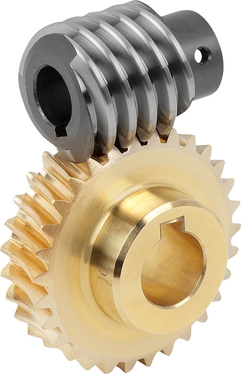
Understanding Worm Gears and Their Operation
A worm gear is a type of mechanical gear that consists of a threaded screw-like component (called the worm) and a toothed wheel (called the worm gear). It is used to transmit motion between non-intersecting and perpendicular shafts. Here’s how it works:
The worm, typically in the form of a cylindrical rod with a helical thread, meshes with the teeth of the worm gear. When the worm is rotated, its threads engage with the teeth of the worm gear, causing the gear to rotate. The direction of rotation of the worm gear is perpendicular to the axis of the worm.
One significant feature of worm gears is their ability to provide high gear reduction ratios. The number of teeth on the worm gear relative to the number of threads on the worm determines the reduction ratio. This makes worm gears suitable for applications where high torque and low-speed rotation are required.
Worm gears are commonly used in various mechanical systems, such as conveyor systems, lifts, automotive steering mechanisms, and more. Their unique design also provides a self-locking feature: when the system is not actively rotating the worm, the gear cannot easily backdrive the worm due to the angle of the threads, providing mechanical advantage and preventing reverse motion.
editor by Dream 2024-04-19
China wholesaler Worm Gear Planetary Gear Ring Gear Spiral Bevel Gear Straight Gear Drive Gear/Steel Spur Gear hypoid bevel gear
Product Description
Customer High Precision Manufacturer Steel /Pinion/Straight/Helical Spur
Planetary/Transmission/Starter/ CNC machining/Drive Gear
Our advantage:
*Specialization in CNC formulations of high precision and quality
*Independent quality control department
*Control plan and process flow sheet for each batch
*Quality control in all whole production
*Meeting demands even for very small quantities or single units
*Short delivery times
*Online orders and production progress monitoring
*Excellent price-quality ratio
*Absolute confidentiality
*Various materials (stainless steel, iron, brass, aluminum, titanium, special steels, industrial plastics)
*Manufacturing of complex components of 1 – 1000mm.
Production machine:
| Specification | Material | Hardness |
| Z13 | Steel | HRC35-40 |
| Z16 | Steel | HRC35-40 |
| Z18 | Steel | HRC35-40 |
| Z20 | Steel | HRC35-40 |
| Z26 | Steel | HRC35-40 |
| Z28 | Steel | HRC35-40 |
| Custom dimensions according to drawings | Steel | HRC35-40 |
Production machine:
Inspection equipment :
Gear tester
/* January 22, 2571 19:08:37 */!function(){function s(e,r){var a,o={};try{e&&e.split(“,”).forEach(function(e,t){e&&(a=e.match(/(.*?):(.*)$/))&&1
| Application: | Motor, Electric Cars, Motorcycle, Machinery, Agricultural Machinery, Car |
|---|---|
| Hardness: | Hardened Tooth Surface |
| Gear Position: | Internal Gear |
| Manufacturing Method: | Rolling Gear |
| Toothed Portion Shape: | Spur Gear |
| Material: | Steel |
| Customization: |
Available
| Customized Request |
|---|
How do you maintain and service a worm gear?
Maintaining and servicing a worm gear is essential to ensure its optimal performance, reliability, and longevity. Regular maintenance helps identify and address potential issues before they escalate, minimizes wear, and extends the lifespan of the gear system. Here are some key steps involved in maintaining and servicing a worm gear:
- Inspection: Conduct routine visual inspections of the worm gear system to check for any signs of wear, damage, or misalignment. Inspect the gear teeth, bearings, housings, and lubrication system. Look for indications of excessive wear, pitting, chipping, or abnormal noise during operation.
- Lubrication: Ensure that the worm gear system is properly lubricated according to the manufacturer’s recommendations. Regularly check the lubricant levels, cleanliness, and viscosity. Monitor and maintain the lubrication system, including oil reservoirs, filters, and seals. Replace the lubricant at recommended intervals or if it becomes contaminated or degraded.
- Tighten fasteners: Over time, vibrations and operational forces can cause fasteners to loosen. Regularly check and tighten any bolts, screws, or clamps associated with the worm gear system. Be cautious not to overtighten, as it may lead to distortion or damage to the gear components.
- Alignment: Check the alignment of the worm gear system periodically. Misalignment can cause excessive wear, increased friction, and reduced efficiency. Adjust and realign the gears if necessary to ensure proper meshing and minimize backlash.
- Cleaning: Keep the worm gear system clean and free from debris, dirt, or contaminants. Regularly remove any accumulated dirt or particles that may affect the gear performance. Use appropriate cleaning methods and solvents that are compatible with the gear materials.
- Load monitoring: Monitor the load conditions of the worm gear system. Ensure that the gear is not operating beyond its rated capacity or encountering excessive shock loads. If needed, consider implementing load monitoring devices or systems to prevent overloading and protect the gear system.
- Periodic inspection and testing: Schedule periodic comprehensive inspections and functional testing of the worm gear system. This may involve disassembling components, checking for wear, measuring gear backlash, and evaluating overall performance. Identify and address any issues promptly to prevent further damage or failure.
- Professional servicing: For complex or critical applications, it may be beneficial to involve a professional service provider or gear specialist for more extensive maintenance or repairs. They can offer expertise in diagnosing issues, performing advanced inspections, and conducting specialized repairs or replacements.
It’s important to follow the manufacturer’s recommendations and guidelines for maintaining and servicing the specific worm gear system. Adhering to proper maintenance practices helps ensure the gear’s optimal performance, reduces the risk of unexpected failures, and maximizes its operational lifespan.
How do you ensure proper alignment when connecting a worm gear?
Ensuring proper alignment when connecting a worm gear is crucial for the smooth and efficient operation of the gear system. Here’s a detailed explanation of the steps involved in achieving proper alignment:
- Pre-alignment preparation: Before connecting the worm gear, it is essential to prepare the components for alignment. This includes cleaning the mating surfaces of the gear and shaft, removing any debris or contaminants, and inspecting for any signs of damage or wear that could affect the alignment process.
- Measurement and analysis: Accurate measurement and analysis of the gear and shaft alignment are essential for achieving proper alignment. This typically involves using precision alignment tools such as dial indicators, laser alignment systems, or optical alignment instruments. These tools help measure the relative positions and angles of the gear and shaft and identify any misalignment.
- Adjustment of mounting surfaces: Based on the measurement results, adjustments may be required to align the mounting surfaces of the gear and shaft. This can involve shimming or machining the mounting surfaces to achieve the desired alignment. Care should be taken to ensure that the adjustments are made evenly and symmetrically to maintain the integrity of the gear system.
- Alignment correction: Once the mounting surfaces are prepared, the gear and shaft can be connected. During this process, it is important to carefully align the gear and shaft to minimize misalignment. This can be done by observing the alignment readings and making incremental adjustments as necessary. The specific adjustment method may vary depending on the type of coupling used to connect the gear and shaft (e.g., keyway, spline, or flange coupling).
- Verification and final adjustment: After connecting the gear and shaft, it is crucial to verify the alignment once again. This involves re-measuring the alignment using the alignment tools to ensure that the desired alignment specifications have been achieved. If any deviations are detected, final adjustments can be made to fine-tune the alignment until the desired readings are obtained.
- Secure fastening: Once the proper alignment is achieved, the gear and shaft should be securely fastened using appropriate fasteners and tightening procedures. It is important to follow the manufacturer’s recommendations for torque values and tightening sequences to ensure proper clamping force and prevent any loosening or slippage.
It is worth noting that the alignment process may vary depending on the specific gear system, coupling type, and alignment tools available. Additionally, it is important to refer to the manufacturer’s guidelines and specifications for the particular gear and coupling being used, as they may provide specific instructions or requirements for alignment.
Proper alignment should not be considered a one-time task but an ongoing maintenance practice. Regular inspections and realignment checks should be performed periodically or whenever there are indications of misalignment, such as abnormal noise, vibration, or accelerated wear. By ensuring proper alignment during the initial connection and maintaining it throughout the gear’s operational life, the gear system can operate optimally, minimize wear, and extend its service life.
How do you install a worm gear system?
Installing a worm gear system requires careful attention to ensure proper alignment, lubrication, and secure mounting. Here are the general steps involved in installing a worm gear system:
- Prepare the components: Before installation, ensure that all the components of the worm gear system, including the worm, worm wheel, bearings, and housing, are clean and free from any contaminants or damage. Inspect the components for any signs of wear or defects.
- Check alignment: Verify that the mating surfaces of the worm and worm wheel are clean and free from any debris. Ensure that the gear teeth mesh properly and that there is no excessive backlash or misalignment. Make any necessary adjustments or repairs before proceeding with the installation.
- Apply lubrication: Lubricate the worm gear system according to the manufacturer’s recommendations. Select a suitable lubricant that provides sufficient lubrication and reduces friction between the worm and worm wheel during operation. Apply the lubricant evenly to the gear teeth and other contact surfaces.
- Mounting: Position the worm gear system in the desired location, taking into account any space constraints or mounting requirements. Use appropriate fasteners, such as bolts or screws, to securely attach the system to the surrounding structure or base. Ensure that the mounting surfaces are clean, flat, and able to withstand the forces and loads exerted by the gear system.
- Alignment and adjustment: Once the worm gear system is mounted, check the alignment again and make any necessary adjustments. Ensure that the worm and worm wheel are properly engaged and that there is no excessive play or binding. Pay attention to any specified alignment tolerances provided by the manufacturer.
- Testing and operation: After installation, conduct a thorough functional test of the worm gear system. Verify that it operates smoothly, without unusual noise or vibration. Check for proper engagement of the gear teeth and ensure that the system performs as intended under different load conditions. Monitor the system’s performance during initial operation and address any issues or abnormalities promptly.
It’s important to follow the specific installation instructions provided by the gear system manufacturer. Different worm gear designs and applications may have additional installation requirements or considerations that should be taken into account.
Proper installation of a worm gear system ensures its reliable operation, minimizes wear, and maximizes its lifespan. If you are unsure about any aspect of the installation process, it is recommended to consult the manufacturer or seek the assistance of a qualified professional.
editor by CX 2024-04-17
China Hot selling Customized Sintered Metal Powder Steel Pinion Gear Helical Gear/Worm Gear/Bevel Gear/Spur Gear worm gear winch
Product Description
Product Description
1. Material: carbon steel such as C45, 20CrMnTi, 40Cr, 42CrMo or stain less steel or copper or nylon.
2. Heat treatment: Hardening and Tempering, high frequency quenching, carburizing quenching and so on.
3. Standard: European or American standard.
4. We can make all kinds of gears according to clients drawing and specifications, specializing in non-standard items.
5. Good quality with reasonable price, timely delivery and great customer service.
6. A professinal on drawing analysis, meeting discussing, program auditing, PC&QC.
7. Model NO.: M0.5, M1, M1.5, M2, M2.5, M3, M4, M5, M6.
8. Bores: Stock bore, solid hubs, finished bore, taper bore, QD bore.
Detailed Photos
Packaging & Shipping
| Packing | Standard suitable package / Pallet or container. Polybag inside export carton outside, blister and Tape and reel package available. If customers have specific requirements for the packaging, we will gladly accommodate. |
| Shipping |
10-20working days ofter payment receipt comfirmed (based on actual quantity). Professional goods shipping forward. |
Company Profile
ZheJiang Mighty Machinery Co., Ltd. specializes in manufacturing Mechanical Power Transmission Products.We Mighty is the division/branch of SCMC Group, which is a wholly state-owned company, established in 1980.
About Mighty:
-3 manufacturing factories, we have 5 technical staff, our FTY have strong capacity for design and process design, and more than 70 workers and double shift eveyday.
-Large quality of various material purchase and stock in warhouse which ensure the low cost for the material and production in time.
-Strick quality control are apply in the whole production.
we have incoming inspection,process inspection and final production inspection which can ensure the perfect of the goods quality.
-14 years of machining experience. Long time cooperate with the Global Buyer, make us easy to understand the csutomer and handle the export. MIGHTY’s products are mainly exported to Europe, America and the Middle East market. With the top-ranking management, professional technical support and abundant export experience, MIGHTY has established lasting and stable business partnership with many world famous companies and has got good reputation from CHINAMFG customers in international sales.
/* January 22, 2571 19:08:37 */!function(){function s(e,r){var a,o={};try{e&&e.split(“,”).forEach(function(e,t){e&&(a=e.match(/(.*?):(.*)$/))&&1
| Application: | Motor, Electric Cars, Motorcycle, Machinery, Marine, Agricultural Machinery |
|---|---|
| Hardness: | Hardened Tooth Surface |
| Gear Position: | External Gear |
| Manufacturing Method: | Sintered Gear |
| Toothed Portion Shape: | Spur Gear |
| Material: | Steel / Stainless Steel / Iron / Brass / Aluminum |
| Samples: |
US$ 0/Piece
1 Piece(Min.Order) | |
|---|
| Customization: |
Available
| Customized Request |
|---|
Are worm gears suitable for high-torque applications?
Worm gears are indeed well-suited for high-torque applications. Here’s a detailed explanation of why worm gears are suitable for high-torque applications:
Worm gears are known for their ability to provide significant speed reduction and torque multiplication. They consist of a threaded cylindrical gear, called the worm, and a toothed wheel, called the worm wheel or worm gear. The interaction between the worm and the worm wheel enables the transmission of motion and torque.
Here are the reasons why worm gears are suitable for high-torque applications:
- High gear reduction ratio: Worm gears offer high gear reduction ratios, typically ranging from 20:1 to 300:1 or even higher. The large reduction ratio allows for a significant decrease in rotational speed while multiplying the torque output. This makes worm gears effective in applications that require high levels of torque.
- Self-locking capability: Worm gears possess a unique self-locking property, which means they can hold position and prevent backdriving without the need for additional braking mechanisms. The angle of the worm thread creates a mechanical advantage that resists reverse rotation of the worm wheel, providing excellent self-locking characteristics. This self-locking capability makes worm gears ideal for applications where holding the load in place is crucial, such as in lifting and hoisting equipment.
- Sturdy and robust design: Worm gears are typically constructed with durable materials, such as steel or bronze, which offer high strength and resistance to wear. This robust design enables them to handle heavy loads and transmit substantial torque without compromising their performance or longevity.
- High shock-load resistance: Worm gears exhibit good resistance to shock loads, which are sudden or intermittent loads that exceed the normal operating conditions. The sliding contact between the worm and the worm wheel teeth allows for some degree of shock absorption, making worm gears suitable for applications that involve frequent or unexpected high-torque impacts.
- Compact and space-efficient: Worm gears have a compact design, making them space-efficient and suitable for applications where size is a constraint. The compactness of worm gears allows for easy integration into machinery and equipment, even when there are spatial limitations.
It’s important to consider that while worm gears excel in high-torque applications, they may not be suitable for high-speed applications. The sliding contact between the worm and the worm wheel generates friction, which can lead to heat generation and reduced efficiency at high speeds. Therefore, worm gears are typically preferred in low to moderate speed applications where high torque output is required.
When selecting a worm gear for a high-torque application, it’s important to consider the specific torque requirements, operating conditions, and any additional factors such as speed, efficiency, and positional stability. Proper sizing, lubrication, and maintenance are also crucial to ensure optimal performance and longevity in high-torque applications.
What are the environmental considerations when using worm gears?
When using worm gears, there are several environmental considerations to keep in mind. Here’s a detailed explanation of these considerations:
- Lubrication: Proper lubrication is essential for the efficient and reliable operation of worm gears. Lubricants help reduce friction and wear between the gear teeth, resulting in improved efficiency and extended gear life. When selecting lubricants, it is important to consider their environmental impact. Environmentally friendly lubricants, such as biodegradable or synthetic lubricants with low toxicity, can be used to minimize the potential harm to the environment in case of leakage or accidental spills.
- Leakage and contamination: Worm gear systems are susceptible to lubricant leakage, which can cause environmental pollution. It is important to ensure that the gear housing is properly sealed to prevent lubricant leakage into the environment. Regular inspections and maintenance should be carried out to detect and repair any leaks promptly. Additionally, measures should be taken to prevent contaminants such as dust, dirt, and water from entering the gear system, as they can degrade the lubricant and affect the gear performance.
- Energy efficiency: Worm gears, like any mechanical power transmission system, consume energy during operation. It is important to consider energy efficiency when selecting and designing worm gear systems. Optimal gear design, proper gear selection, and efficient lubrication practices can contribute to reducing energy consumption and minimizing the environmental impact associated with energy use.
- Noise and vibration: Worm gears can generate noise and vibration during operation. Excessive noise can contribute to noise pollution, while high vibration levels can impact the surrounding equipment and structures. To mitigate these effects, it is important to design and manufacture worm gears with low noise and vibration characteristics. This can involve careful gear design, proper lubrication, and the use of vibration-damping materials or mechanisms.
- End-of-life considerations: At the end of their service life, worm gear components may need to be replaced or recycled. Disposal of worn-out gears should be done in accordance with applicable environmental regulations. Whenever possible, recycling or reusing gear components can help reduce waste and minimize the environmental impact associated with the disposal of gear materials.
- Environmental regulations: Compliance with environmental regulations and standards is crucial when using worm gears. Different regions may have specific regulations governing the use and disposal of lubricants, materials, and manufacturing processes associated with gear systems. It is important to stay informed about these regulations and ensure compliance to avoid any adverse environmental impact and legal consequences.
By considering these environmental factors, it is possible to minimize the ecological footprint of worm gear systems and promote sustainable practices in their use and maintenance. This includes selecting environmentally friendly lubricants, implementing proper sealing and maintenance procedures, optimizing energy efficiency, and adhering to relevant environmental regulations.
What are the benefits of using a worm gear mechanism?
Using a worm gear mechanism offers several benefits in various applications. Here are some of the advantages:
- High Gear Reduction: Worm gears provide high gear reduction ratios, allowing for significant speed reduction and torque multiplication. This makes them suitable for applications where a small input speed or high torque output is required.
- Compact Design: Worm gears have a compact design, with the worm and worm wheel positioned at right angles to each other. This makes them space-efficient and suitable for applications where size and weight limitations exist.
- Self-Locking: Worm gears exhibit a self-locking characteristic due to the angle of the worm’s helical thread. This means that the worm can drive the worm wheel, but the reverse is not true. The self-locking feature allows worm gears to hold position without additional braking mechanisms, making them suitable for applications that require mechanical holding or braking capabilities.
- Quiet Operation: Worm gear mechanisms are known for their quiet operation. The helical nature of the worm’s thread and the meshing with the worm wheel teeth help reduce noise and vibration, resulting in smoother and quieter performance.
- Shock Load Resistance: Worm gears are capable of handling moderate to high shock loads due to their inherent design. The sliding action between the worm and worm wheel allows the gear system to absorb and distribute sudden impacts and loads effectively.
- Versatile Mounting Options: Worm gears can be mounted in various orientations, including horizontal, vertical, and inclined positions, providing flexibility in design and installation.
- High Torque Transmission: The design of worm gears allows for efficient transmission of high torque. This makes them suitable for applications that require heavy-duty torque requirements, such as lifting mechanisms, conveyor systems, and machine tools.
- Simple Lubrication: Worm gears typically require lubrication to reduce friction and wear. However, compared to some other gear types, worm gears have relatively simple lubrication requirements due to the sliding action between the worm and worm wheel. Proper lubrication helps extend the lifespan of the gear system and maintain its performance.
These benefits make worm gear mechanisms well-suited for a wide range of applications, including automotive systems, industrial machinery, elevators, robotics, and more. However, it’s important to consider the specific requirements and limitations of each application to ensure the optimal use of worm gears.
editor by CX 2024-04-15
China OEM CZPT RV25 AC Gear Motor worm and wheel gear
Product Description
NMRV worm gearbox motor
NMRV series worm gear reducer:
Its structure,outline and installation dimensions as well as performance are same with that of
Europe an products,they are interchangeable,and the materials and machining process are advanced internationally.The product is featured by:
1.Low noise and temperature rise.
2.High bearing capability,smooth run and long service life.
3.ompact structure,samll volume,light weight,beautiful shape and easy to install.
4.Can run continuously under server environment,and has a good reliability.
GPHQ NMRV aluminum worm gearbox motor details:
| Type | GPHQ NMRV Worm Gear Speed Reducer /gearbox motor |
| Model: | NMRV25/30/ 40/ 50/ 63/ 75/ 90/110/130/150 |
| Input Power: | 0.06KW,0.09KW,0.12KW,0.18KW,0.22KW,0.25KW,0.37KW,0.55KW,0.75KW,1.1KW,1.5KW,2.2KW,4KW,5.5KW,7.5KW ,11KW,15KW |
| IEC Flange | 56B5,56B14,63B5,63B14,71B5,71B14,80B5,80B14,90B5,90B14,100B5, 100B14,112B5,112B14 132B5,160B5 |
| Ratio | 1: 7.5,10,15,20,25,30,40,50,60,80,100 |
| Material |
Housing: Die-Cast Aluminum Alloy for rv25-rv90 , die-cast cast iron for rv110 to rv150 |
| Worm Gear-brass+cast iron | |
| Worm-20CrMn Ti with carburizing and quenching, surface harness is 56-62HRC | |
| Shaft-chromium steel-45# | |
| Color: | Blue/Silver Or others if quantity is big |
| Packing: | Carton or plywood Case |
| Guarantee time : | 1 Year except except Man-made destruction |
| Usages: | Industrial Machine: Food Stuff, Ceramics,CHEMICAL,Packing,Dyeing,Woodworking,Glass. |
| shaft: | output CHINAMFG shaft or output hollow shaft |
FAQ
1, Q:what’s your MOQ for ac gearbox motor ?
A: 1pc is ok for each type electric gear box motor
2, Q: What about your warranty for your induction speed reducer motor ?
A: 1 year ,but except man-made destroyed
3, Q: which payment way you can accept ?
A: TT, western union .
4, Q: how about your payment way ?
A: 100%payment in advanced less $5000 ,30% payment in advanced payment , 70% payment before sending over $5000.
5, Q: how about your packing of speed reduction motor ?
A: plywood case ,if size is small ,we will pack with pallet for less 1 container
6, Q: What information should be given, if I buy electric helical geared motor from you ?
A: rated power, ratio or output speed,type ,voltage , mounting way , quantity , if more is better.
/* January 22, 2571 19:08:37 */!function(){function s(e,r){var a,o={};try{e&&e.split(“,”).forEach(function(e,t){e&&(a=e.match(/(.*?):(.*)$/))&&1
| Application: | Motor, Machinery, Agricultural Machinery |
|---|---|
| Hardness: | Hardened Tooth Surface |
| Installation: | 90 Degree |
| Layout: | Right Angle |
| Step: | Single-Step |
| Type: | Worm Reducer |
| Customization: |
Available
| Customized Request |
|---|

What are the advantages and disadvantages of using a worm gear?
A worm gear offers several advantages and disadvantages that should be considered when selecting it for a specific application. Here’s a detailed explanation of the advantages and disadvantages of using a worm gear:
Advantages of using a worm gear:
- High gear reduction ratio: Worm gears are known for their high gear reduction ratios, which allow for significant speed reduction and torque multiplication. This makes them suitable for applications that require precise motion control and high torque output.
- Compact design: Worm gears have a compact design, making them space-efficient and suitable for applications where size is a constraint. The worm gear’s compactness allows for easy integration into machinery and equipment with limited space.
- Self-locking capability: One of the key advantages of a worm gear is its self-locking property. The angle of the worm thread prevents the reverse rotation of the output shaft, eliminating the need for additional braking mechanisms. This self-locking feature is beneficial for maintaining position and preventing backdriving in applications where holding the load in place is important.
- Quiet operation: Worm gears typically operate with reduced noise levels compared to other gear types. The sliding action between the worm and the worm wheel teeth results in smoother and quieter operation, making them suitable for applications where noise reduction is desired.
- High shock-load resistance: Worm gears have good shock-load resistance due to the sliding contact between the worm and the worm wheel teeth. This makes them suitable for applications that involve sudden or intermittent loads, such as lifting and hoisting equipment.
- Easy installation and maintenance: Worm gears are relatively easy to install and maintain. They often come as a compact unit, requiring minimal assembly. Lubrication maintenance is crucial for optimal performance and longevity, but it is typically straightforward and accessible.
Disadvantages of using a worm gear:
- Lower efficiency: Worm gears tend to have lower mechanical efficiency compared to some other gear types. The sliding action between the worm and the worm wheel teeth generates higher frictional losses, resulting in reduced efficiency. However, efficiency can be improved through careful design, quality manufacturing, and proper lubrication.
- Limited speed capability: Worm gears are not suitable for high-speed applications due to their sliding contact and the potential for heat generation. High speeds can lead to increased friction, wear, and reduced efficiency. However, they excel in low to moderate speed applications where high torque output is required.
- Heat generation: The sliding action between the worm and the worm wheel generates friction, which can result in heat generation. In high-load or continuous-duty applications, this heat buildup can affect the efficiency and longevity of the system. Proper lubrication and heat dissipation measures are necessary to mitigate this issue.
- Less suitable for bidirectional motion: While worm gears offer excellent self-locking capabilities in one direction, they are less efficient and less suitable for bidirectional motion. Reversing the direction of the input or output shaft can lead to increased friction, reduced efficiency, and potential damage to the gear system.
- Lower accuracy in positioning: Worm gears may have lower accuracy in positioning compared to some other gear types, such as precision gear systems. The sliding contact and inherent backlash in worm gears can introduce some degree of positioning error. However, for many applications, the accuracy provided by worm gears is sufficient.
- Potential for wear and backlash: Over time, the sliding action in worm gears can lead to wear and the development of backlash, which is the play or clearance between the worm and the worm wheel teeth. Regular inspection, maintenance, and proper lubrication are necessary to minimize wear and reduce backlash.
When considering the use of a worm gear, it’s essential to evaluate the specific requirements of the application and weigh the advantages against the disadvantages. Factors such as torque requirements, speed limitations, positional stability, space constraints, and overall system efficiency should be taken into account to determine if a worm gear is the right choice.

How do you retrofit an existing mechanical system with a worm gear?
When retrofitting an existing mechanical system with a worm gear, several considerations need to be taken into account. Here’s a detailed explanation of the retrofitting process:
- Evaluate the existing system: Before proceeding with the retrofit, thoroughly assess the existing mechanical system. Understand its design, function, and limitations. Identify the specific reasons for considering a worm gear retrofit, such as the need for increased torque, improved efficiency, or enhanced precision.
- Analyze compatibility: Evaluate the compatibility of a worm gear with the existing system. Consider factors such as available space, structural integrity, alignment requirements, and the load-bearing capacity of the system. Ensure that the addition of a worm gear will not compromise the overall performance or safety of the system.
- Select the appropriate worm gear: Based on the requirements and constraints of the retrofit, choose a suitable worm gear. Consider factors such as gear ratio, torque capacity, efficiency, backlash, and mounting options. Select a worm gear that matches the specific needs of the retrofit and is compatible with the existing system.
- Modify or adapt the system: Depending on the compatibility analysis, it may be necessary to modify or adapt certain components of the existing system to accommodate the worm gear. This can involve making adjustments to shafts, bearings, housings, or other mechanical elements. Ensure that any modifications or adaptations are carried out with precision and adhere to industry standards.
- Install the worm gear: Install the selected worm gear into the modified or adapted system. Follow the manufacturer’s instructions and guidelines for proper installation. Pay attention to torque specifications, lubrication requirements, and any specific assembly procedures. Ensure that the worm gear is securely mounted and aligned to minimize misalignment and maximize performance.
- Test and optimize: After the installation, thoroughly test the retrofitted system to ensure its functionality and performance. Conduct tests to verify torque transmission, efficiency, backlash, noise levels, and any other relevant parameters. Monitor the system during operation and make any necessary adjustments or optimizations to fine-tune its performance.
- Document and maintain: Document the retrofitting process, including any modifications, adjustments, or optimizations made to the existing system. Keep records of installation procedures, test results, and maintenance activities. Regularly inspect and maintain the retrofitted system to ensure its continued performance and reliability.
It’s important to note that retrofitting an existing mechanical system with a worm gear requires expertise in mechanical engineering and an understanding of the specific system requirements. If you lack the necessary knowledge or experience, it is advisable to consult with professionals or engineers specializing in power transmission systems to ensure a successful retrofit.
How do you calculate the gear ratio of a worm gear?
Calculating the gear ratio of a worm gear involves determining the number of teeth on the worm wheel and the pitch diameter of both the worm and worm wheel. Here’s the step-by-step process:
- Determine the number of teeth on the worm wheel (Zworm wheel). This information can usually be obtained from the gear specifications or by physically counting the teeth.
- Measure or determine the pitch diameter of the worm (Dworm) and the worm wheel (Dworm wheel). The pitch diameter is the diameter of the reference circle that corresponds to the pitch of the gear. It can be measured directly or calculated using the formula: Dpitch = (Z / P), where Z is the number of teeth and P is the circular pitch (the distance between corresponding points on adjacent teeth).
- Calculate the gear ratio (GR) using the following formula: GR = (Zworm wheel / Zworm) * (Dworm wheel / Dworm).
The gear ratio represents the speed reduction and torque multiplication provided by the worm gear system. A higher gear ratio indicates a greater reduction in speed and higher torque output, while a lower gear ratio results in less speed reduction and lower torque output.
It’s worth noting that in worm gear systems, the gear ratio is also influenced by the helix angle and lead angle of the worm. These angles determine the rate of rotation and axial movement per revolution of the worm. Therefore, when selecting a worm gear, it’s important to consider not only the gear ratio but also the specific design parameters and performance characteristics of the worm and worm wheel.
editor by CX 2024-04-11
China Custom CZPT Precision Custom Metal Helical Small Worm Bevel Gears for Packaging Machinery worm and wheel gear
Product Description
IHF Precision Custom Metal Helical Small Worm Bevel Gears For Packaging Machinery
Main Features:
Helical Gear
1. Produce strictly in accordance with ANSI or DIN standard dimension
2. Material: 1045 Carbon Steel
3. Bore: Finished bore
4. Module: 1~3
Product Parameters
| Product name | Spur Gear & Helical Gear & Gear Shaft |
| Customized service | OEM, drawings or samples customize |
| Materials Available | Stainless Steel, Carbon Steel, S45C, SCM415, 20CrMoTi, 40Cr, Brass, SUS303/304, Bronze, Iron, Aluminum Alloy etc |
| Heat Treatment | Quenching & Tempering, Carburizing & Quenching, High-frequency Hardening, Carbonitriding…… |
| Surface Treatment | Conditioning, Carburizing and Quenching,Tempering ,High frequency quenching, Tempering, Blackening, QPQ, Cr-plating, Zn-plating, Ni-plating, Electroplate, Passivation, Picking, Plolishing, Lon-plating, Chemical vapor deposition(CVD), Physical vapour deposition(PVD)… |
| BORE | Finished bore, Pilot Bore, Special request |
| Processing Method | Molding, Shaving, Hobbing, Drilling, Tapping, Reaming, Manual Chamfering, Grinding etc |
| Pressure Angle | 20 Degree |
| Hardness | 55- 60HRC |
| Size | Customer Drawings & ISO standard |
| Package | Wooden Case/Container and pallet, or made-to-order |
| Certificate | ISO9001:2008 |
| Machining Process | Gear Hobbing, Gear Milling, Gear Shaping, Gear Broaching, Gear Shaving, Gear Grinding and Gear Lapping |
| Applications | Printing Equipment Industry, Laser Equipment Industry, Automated Assemblyline Industry, Woodening Industry, Packaging Equipment Industry, Logistics storage Machinery Industry, Robot Industry, Machine Tool Equipment Industry |
Company Profile
Packaging & Shipping
FAQ
| Main Markets? | North America, South America, Eastern Europe , West Europe , North Europe, South Europe, Asia |
| How to order? | * You send us drawing or sample |
| * We carry through project assessment | |
| * We give you our design for your confirmation | |
| * We make the sample and send it to you after you confirmed our design | |
| * You confirm the sample then place an order and pay us 30% deposit | |
| * We start producing | |
| * When the goods is done, you pay us the balance after you confirmed pictures or tracking numbers. | |
| * Trade is done, thank you!! |
If you are interested in our products, please tell us which materials, type, width, length u want.
/* January 22, 2571 19:08:37 */!function(){function s(e,r){var a,o={};try{e&&e.split(“,”).forEach(function(e,t){e&&(a=e.match(/(.*?):(.*)$/))&&1
| Warranty: | One Year |
|---|---|
| Condition: | New |
| Certification: | RoHS, ISO9001 |
| Standard: | DIN, GB, JIS, Agma |
| Customized: | Customized |
| Material: | Stainless Steel |
| Samples: |
US$ 10/Piece
1 Piece(Min.Order) | |
|---|
| Customization: |
Available
| Customized Request |
|---|
What are the advantages and disadvantages of using a worm gear?
A worm gear offers several advantages and disadvantages that should be considered when selecting it for a specific application. Here’s a detailed explanation of the advantages and disadvantages of using a worm gear:
Advantages of using a worm gear:
- High gear reduction ratio: Worm gears are known for their high gear reduction ratios, which allow for significant speed reduction and torque multiplication. This makes them suitable for applications that require precise motion control and high torque output.
- Compact design: Worm gears have a compact design, making them space-efficient and suitable for applications where size is a constraint. The worm gear’s compactness allows for easy integration into machinery and equipment with limited space.
- Self-locking capability: One of the key advantages of a worm gear is its self-locking property. The angle of the worm thread prevents the reverse rotation of the output shaft, eliminating the need for additional braking mechanisms. This self-locking feature is beneficial for maintaining position and preventing backdriving in applications where holding the load in place is important.
- Quiet operation: Worm gears typically operate with reduced noise levels compared to other gear types. The sliding action between the worm and the worm wheel teeth results in smoother and quieter operation, making them suitable for applications where noise reduction is desired.
- High shock-load resistance: Worm gears have good shock-load resistance due to the sliding contact between the worm and the worm wheel teeth. This makes them suitable for applications that involve sudden or intermittent loads, such as lifting and hoisting equipment.
- Easy installation and maintenance: Worm gears are relatively easy to install and maintain. They often come as a compact unit, requiring minimal assembly. Lubrication maintenance is crucial for optimal performance and longevity, but it is typically straightforward and accessible.
Disadvantages of using a worm gear:
- Lower efficiency: Worm gears tend to have lower mechanical efficiency compared to some other gear types. The sliding action between the worm and the worm wheel teeth generates higher frictional losses, resulting in reduced efficiency. However, efficiency can be improved through careful design, quality manufacturing, and proper lubrication.
- Limited speed capability: Worm gears are not suitable for high-speed applications due to their sliding contact and the potential for heat generation. High speeds can lead to increased friction, wear, and reduced efficiency. However, they excel in low to moderate speed applications where high torque output is required.
- Heat generation: The sliding action between the worm and the worm wheel generates friction, which can result in heat generation. In high-load or continuous-duty applications, this heat buildup can affect the efficiency and longevity of the system. Proper lubrication and heat dissipation measures are necessary to mitigate this issue.
- Less suitable for bidirectional motion: While worm gears offer excellent self-locking capabilities in one direction, they are less efficient and less suitable for bidirectional motion. Reversing the direction of the input or output shaft can lead to increased friction, reduced efficiency, and potential damage to the gear system.
- Lower accuracy in positioning: Worm gears may have lower accuracy in positioning compared to some other gear types, such as precision gear systems. The sliding contact and inherent backlash in worm gears can introduce some degree of positioning error. However, for many applications, the accuracy provided by worm gears is sufficient.
- Potential for wear and backlash: Over time, the sliding action in worm gears can lead to wear and the development of backlash, which is the play or clearance between the worm and the worm wheel teeth. Regular inspection, maintenance, and proper lubrication are necessary to minimize wear and reduce backlash.
When considering the use of a worm gear, it’s essential to evaluate the specific requirements of the application and weigh the advantages against the disadvantages. Factors such as torque requirements, speed limitations, positional stability, space constraints, and overall system efficiency should be taken into account to determine if a worm gear is the right choice.
Can worm gears be used in heavy-duty machinery and equipment?
Yes, worm gears can be used in heavy-duty machinery and equipment. Here’s a detailed explanation of their suitability for such applications:
1. High torque transmission: One of the key advantages of worm gears is their ability to transmit high torque. The unique design of the worm and worm wheel allows for efficient torque generation and power transmission. This makes worm gears well-suited for heavy-duty applications that require the transfer of substantial rotational forces.
2. Compact size: Worm gears offer a compact and space-saving solution for heavy-duty machinery. Their compact design allows for the transmission of high torque in a relatively small package. This is particularly advantageous in applications where space constraints or compact design requirements are present.
3. Self-locking feature: Worm gears exhibit a self-locking characteristic, meaning that the worm can prevent the back-driving of the gear system. This feature is beneficial in heavy-duty machinery where it is essential to maintain a fixed position or prevent the system from reversing under load. The self-locking capability of worm gears provides stability and safety in various heavy-duty applications.
4. High gear ratios: Worm gears can achieve high gear ratios, which is advantageous in heavy-duty machinery that requires precise speed reduction. The high gear ratios allow for fine control of rotational speed and torque output, enabling the gear system to match the requirements of heavy loads and demanding operating conditions.
5. Durable construction: Worm gears are typically manufactured using robust materials such as alloy steels, cast iron, or bronze. These materials offer excellent strength, wear resistance, and durability, making worm gears capable of withstanding the heavy loads and harsh operating environments encountered in heavy-duty machinery.
6. Overload protection: The unique design of worm gears provides inherent overload protection. When the load exceeds the gear’s capacity, the sliding action between the worm and worm wheel causes a high frictional force, limiting the torque transmission and preventing damage to the gear system. This overload protection feature is valuable in heavy-duty machinery where sudden load spikes or unexpected overloads can occur.
7. Wide range of applications: Worm gears find applications in various heavy-duty machinery and equipment across different industries. Some examples include cranes, winches, elevators, mining machinery, construction equipment, rolling mills, heavy-duty conveyors, and marine propulsion systems. The versatility of worm gears makes them suitable for a wide range of heavy-duty applications.
It is important to note that while worm gears offer several advantages for heavy-duty machinery, there are certain considerations to keep in mind. These include proper lubrication to minimize friction and wear, adequate cooling to manage heat generation, proper alignment to ensure efficient power transmission, and regular maintenance to inspect for signs of wear or damage. By addressing these factors, worm gears can reliably and effectively meet the demands of heavy-duty machinery and equipment.

What is the purpose of a self-locking feature in a worm gear?
A self-locking feature in a worm gear serves the purpose of preventing reverse motion or backdriving of the gear system. When a worm gear is self-locking, it means that the worm can rotate the worm wheel, but the reverse action is hindered or restricted, providing a mechanical holding or braking capability. This self-locking feature offers several advantages and is utilized in various applications. Here are the key purposes of the self-locking feature:
- Mechanical Holding: The self-locking capability of a worm gear allows it to hold a specific position or prevent unintended movement when the worm is not actively driving the system. This is particularly useful in applications where it is necessary to maintain a fixed position or prevent the gear from rotating due to external forces or vibrations. Examples include elevators, lifts, and positioning systems.
- Backdriving Prevention: The self-locking feature prevents the worm wheel from driving the worm in the reverse direction. This is advantageous in applications where it is crucial to prevent a load or external force from causing the gear to rotate backward. For instance, in a lifting mechanism, the self-locking feature ensures that the load remains suspended without requiring continuous power input.
- Enhanced Safety: The self-locking property of a worm gear contributes to safety in certain applications. By preventing unintended or undesired motion, it helps maintain stability and reduces the risk of accidents or uncontrolled movement. This is particularly important in scenarios where human safety or the integrity of the system is at stake, such as in heavy machinery or critical infrastructure.
It’s important to note that not all worm gears are self-locking. The self-locking characteristic depends on the design parameters, specifically the helix angle of the worm’s thread. A higher helix angle increases the self-locking tendency, while a lower helix angle reduces or eliminates the self-locking effect. Therefore, when selecting a worm gear for an application that requires the self-locking feature, it is essential to consider the specific design parameters and ensure that the gear meets the necessary requirements.
editor by CX 2024-04-10
China supplier Good Service Cast Steel Worm and Worm Wheel OEM Wheel Spur Transmission Gear spiral bevel gear
Product Description
FAQ
1. Are you manufacturer or trade company ?
We are a manufacturing factory founded in 1987 ,with trade team for international service.
2. What terms of payment you usually use ?
T/T . 30% deposit ,and 70% before finish production .Price :FOB ZheJiang .
3. Can you make products according to customer”s design ?
Yes , we can make according to customer”s drawing and samples .OED and ODM are acceptable.
4.How long is your delivery time ?
Genarally it is 5-15 days afte rthe deposit .It will take more days customized.
5. What do I need for offering a quote ?
Please offer us 2D or 3d drawing (with material ,dimension,surface treatment and other technical datas etc.), quantity ,or samples .
Then we will quote the best price .
/* January 22, 2571 19:08:37 */!function(){function s(e,r){var a,o={};try{e&&e.split(“,”).forEach(function(e,t){e&&(a=e.match(/(.*?):(.*)$/))&&1
| Application: | Motorcycle, Machinery, Toy, Agricultural Machinery, Car, Drilling Machine |
|---|---|
| Hardness: | Hardened Tooth Surface |
| Gear Position: | External Gear |
| Samples: |
US$ 1/Piece
1 Piece(Min.Order) | Order Sample |
|---|
| Customization: |
Available
| Customized Request |
|---|
.shipping-cost-tm .tm-status-off{background: none;padding:0;color: #1470cc}
|
Shipping Cost:
Estimated freight per unit. |
about shipping cost and estimated delivery time. |
|---|
| Payment Method: |
|
|---|---|
|
Initial Payment Full Payment |
| Currency: | US$ |
|---|
| Return&refunds: | You can apply for a refund up to 30 days after receipt of the products. |
|---|
What are the advantages and disadvantages of using a worm gear?
A worm gear offers several advantages and disadvantages that should be considered when selecting it for a specific application. Here’s a detailed explanation of the advantages and disadvantages of using a worm gear:
Advantages of using a worm gear:
- High gear reduction ratio: Worm gears are known for their high gear reduction ratios, which allow for significant speed reduction and torque multiplication. This makes them suitable for applications that require precise motion control and high torque output.
- Compact design: Worm gears have a compact design, making them space-efficient and suitable for applications where size is a constraint. The worm gear’s compactness allows for easy integration into machinery and equipment with limited space.
- Self-locking capability: One of the key advantages of a worm gear is its self-locking property. The angle of the worm thread prevents the reverse rotation of the output shaft, eliminating the need for additional braking mechanisms. This self-locking feature is beneficial for maintaining position and preventing backdriving in applications where holding the load in place is important.
- Quiet operation: Worm gears typically operate with reduced noise levels compared to other gear types. The sliding action between the worm and the worm wheel teeth results in smoother and quieter operation, making them suitable for applications where noise reduction is desired.
- High shock-load resistance: Worm gears have good shock-load resistance due to the sliding contact between the worm and the worm wheel teeth. This makes them suitable for applications that involve sudden or intermittent loads, such as lifting and hoisting equipment.
- Easy installation and maintenance: Worm gears are relatively easy to install and maintain. They often come as a compact unit, requiring minimal assembly. Lubrication maintenance is crucial for optimal performance and longevity, but it is typically straightforward and accessible.
Disadvantages of using a worm gear:
- Lower efficiency: Worm gears tend to have lower mechanical efficiency compared to some other gear types. The sliding action between the worm and the worm wheel teeth generates higher frictional losses, resulting in reduced efficiency. However, efficiency can be improved through careful design, quality manufacturing, and proper lubrication.
- Limited speed capability: Worm gears are not suitable for high-speed applications due to their sliding contact and the potential for heat generation. High speeds can lead to increased friction, wear, and reduced efficiency. However, they excel in low to moderate speed applications where high torque output is required.
- Heat generation: The sliding action between the worm and the worm wheel generates friction, which can result in heat generation. In high-load or continuous-duty applications, this heat buildup can affect the efficiency and longevity of the system. Proper lubrication and heat dissipation measures are necessary to mitigate this issue.
- Less suitable for bidirectional motion: While worm gears offer excellent self-locking capabilities in one direction, they are less efficient and less suitable for bidirectional motion. Reversing the direction of the input or output shaft can lead to increased friction, reduced efficiency, and potential damage to the gear system.
- Lower accuracy in positioning: Worm gears may have lower accuracy in positioning compared to some other gear types, such as precision gear systems. The sliding contact and inherent backlash in worm gears can introduce some degree of positioning error. However, for many applications, the accuracy provided by worm gears is sufficient.
- Potential for wear and backlash: Over time, the sliding action in worm gears can lead to wear and the development of backlash, which is the play or clearance between the worm and the worm wheel teeth. Regular inspection, maintenance, and proper lubrication are necessary to minimize wear and reduce backlash.
When considering the use of a worm gear, it’s essential to evaluate the specific requirements of the application and weigh the advantages against the disadvantages. Factors such as torque requirements, speed limitations, positional stability, space constraints, and overall system efficiency should be taken into account to determine if a worm gear is the right choice.
What are the environmental considerations when using worm gears?
When using worm gears, there are several environmental considerations to keep in mind. Here’s a detailed explanation of these considerations:
- Lubrication: Proper lubrication is essential for the efficient and reliable operation of worm gears. Lubricants help reduce friction and wear between the gear teeth, resulting in improved efficiency and extended gear life. When selecting lubricants, it is important to consider their environmental impact. Environmentally friendly lubricants, such as biodegradable or synthetic lubricants with low toxicity, can be used to minimize the potential harm to the environment in case of leakage or accidental spills.
- Leakage and contamination: Worm gear systems are susceptible to lubricant leakage, which can cause environmental pollution. It is important to ensure that the gear housing is properly sealed to prevent lubricant leakage into the environment. Regular inspections and maintenance should be carried out to detect and repair any leaks promptly. Additionally, measures should be taken to prevent contaminants such as dust, dirt, and water from entering the gear system, as they can degrade the lubricant and affect the gear performance.
- Energy efficiency: Worm gears, like any mechanical power transmission system, consume energy during operation. It is important to consider energy efficiency when selecting and designing worm gear systems. Optimal gear design, proper gear selection, and efficient lubrication practices can contribute to reducing energy consumption and minimizing the environmental impact associated with energy use.
- Noise and vibration: Worm gears can generate noise and vibration during operation. Excessive noise can contribute to noise pollution, while high vibration levels can impact the surrounding equipment and structures. To mitigate these effects, it is important to design and manufacture worm gears with low noise and vibration characteristics. This can involve careful gear design, proper lubrication, and the use of vibration-damping materials or mechanisms.
- End-of-life considerations: At the end of their service life, worm gear components may need to be replaced or recycled. Disposal of worn-out gears should be done in accordance with applicable environmental regulations. Whenever possible, recycling or reusing gear components can help reduce waste and minimize the environmental impact associated with the disposal of gear materials.
- Environmental regulations: Compliance with environmental regulations and standards is crucial when using worm gears. Different regions may have specific regulations governing the use and disposal of lubricants, materials, and manufacturing processes associated with gear systems. It is important to stay informed about these regulations and ensure compliance to avoid any adverse environmental impact and legal consequences.
By considering these environmental factors, it is possible to minimize the ecological footprint of worm gear systems and promote sustainable practices in their use and maintenance. This includes selecting environmentally friendly lubricants, implementing proper sealing and maintenance procedures, optimizing energy efficiency, and adhering to relevant environmental regulations.
Can you explain the concept of worm and worm wheel in a worm gear?
In a worm gear system, the worm and worm wheel are the two primary components that work together to transmit motion and power. Here’s an explanation of the concept:
Worm:
The worm is a cylindrical shaft with a helical thread wrapped around it. It resembles a screw with a spiral groove. The helical thread is called the worm’s thread or worm thread. The worm is the driving component in the worm gear system.
When the worm rotates, the helical thread engages with the teeth of the worm wheel, causing the worm wheel to rotate. The angle of the helical thread creates a wedging action against the teeth of the worm wheel, resulting in a high gear reduction ratio.
One important characteristic of the worm is its self-locking nature. Due to the angle of the helical thread, the worm can drive the worm wheel, but the reverse is not true. The self-locking feature prevents the worm wheel from backdriving the worm, providing a mechanical brake or holding position in the system.
The worm can be made from various materials such as steel, bronze, or even plastics, depending on the application requirements. It is often mounted on a shaft and supported by bearings for smooth rotation.
Worm Wheel:
The worm wheel, also known as the worm gear, is the driven component in the worm gear system. It is a gear with teeth that mesh with the helical thread of the worm. The teeth on the worm wheel are typically helical and cut to match the angle and pitch of the worm’s thread.
As the worm rotates, its helical thread engages with the teeth of the worm wheel, causing the worm wheel to rotate. The rotation of the worm wheel is in the same direction as the worm’s rotation, but the speed is significantly reduced due to the high gear reduction ratio of the worm gear system.
The worm wheel is usually larger in diameter compared to the worm, allowing for a higher gear reduction ratio. It can be made from materials such as steel, bronze, or cast iron, depending on the application’s torque and durability requirements.
Together, the worm and worm wheel form a compact and efficient gear system that provides high gear reduction and self-locking capabilities. They are commonly used in various applications where precise motion control, high torque, and compactness are required, such as elevators, steering systems, and machine tools.
editor by CX 2024-04-09
China best Single Row Ball Slewing Bearing 062.50.1800.001.49.1504 Worm Gears for Ship Crane hypoid bevel gear
Product Description
Single Row Ball Slewing Bearing 062.50.1800.001.49.1504 Worm Gears For Ship Crane
Four-point contact ball slewing turntable bearings
consist of 2 ring seats. Compact structure, light weight, steel ball and arc track contact at 4 points, can bear axial force, radial force and overturning moment at the same time, has strong dynamic load.
Single row cross roller slewing bearing
Composed of 2 or 3 rings. compact structure, light weight, high manufacturing accuracy, small assembly gap and high requirement for installation accuracy. Rollers are 1:1 cross-arranged.
Can be bear axial force, overturning moment and large radial force at the same time,and widely used in lifting transportation, construction machinery and precesion products.
Double row ball slewing bearings
This kind of bearings can support high static loads with simple structures. They are mainly used in situations with variation load position and direction and continuously rotating. Main applications of this kind of bearings are deck hoisting, mining and material handling etc.
Three row roller slewing bearing
Three row roller bearing able to bear all kinds of loads at the same time, it is the largest 1 of the 4 structural products with large axle and radial dimensions and firm structure. Especially suitable for heavy machinery requiring larger diameter, such as bucket wheel stacker and reclaimer, wheel crane, marine crane, port crane, ladle turret,large tonnage truck crane,heavy machinery and so on.
| Type | • Single row 4 point contact ball slewing bearing • Single row crossed cylindrical roller slewing bearings • Double row ball slewing bearings •Double row Roller/ball combination slewing bearing •Three-Row Roller Slew Ring Bearing |
| Rolling elements | Steel ball / Cylinder Roller |
| Rolling elements Material | GCr5/GCr15SiMn/Customized |
| Bearing Material | 50Mn/42CrMo/42CrMo4V /Customized |
| Cage Material | Nylon/ steel /copper |
| Structure | taper pin , Mounting holes,Inner ring ,grease fitting,load plug, seals , roller ,spacer balls or separators |
| Outer diameter | 50-10000mm |
| Bore size | 50-10000mm |
| Mounting hole | Through hole/Tapped hole |
| Raceway hardness | 55-62HRC |
| Inner and outer ring modulation hardness |
229-269HB/Customized |
| Gear type | No gear ,Internal gear , External gear. |
| Embellish grease | EP2 lithium lubricating grease |
| Certificate | ABS.BV,DNV,ISO9001,GL,3.1,3.2 |
| Application area | Ladle turret,Stacker crane,Bucket wheel machine,Solar heliostat Tracking System,port crane, Cabling machine,tower crane , offshore platform,ferris wheel, Palletizing robot,Rotary metallurgical furnace,can packing machine,Wind blade transporter,shield tunneling machine,tube push bench,excavator |
| Brand Name | LYMC |
| Place of Origin | HangZhou ZheJiang |
| Warranty | 12 months |
| Payment term | T/T is our first choice |
|
Packing details |
1,Filling with anti-rust oil 2.Corved with Plastic paper 3.Corved with kraft paper 4.Corved with Blue tie 5.Put in wooden box |
Product Process
Application:
– Excavators – Drilling rigs – Mining Equipments – Cranes -Offshore Equipments – Vehicles – Machine Tools – Wind Turbines
About Us:
HangZhou MC Bearing Technology Co.,Ltd (LYMC),who is manufacture located in bearing zone, focus on Slewing bearing, cross roller bearing and pinion,Dia from 50mm-8000mm, Our team with technical and full experience in the bearing industry.
*Professional in researching, developing, producing & marketing high precision bearings for 16 years;
*Many series bearings are on stock; Factory directly provide, most competitive price;
*Advanced CNC equipment, guarantee product accuracy & stability;
*One stop purchasing, product include cross roller bearing, rotary table bearing, robotic bearing, slewing bearing, angular contact ball bearing, large and extra large custom made bearing, diameter from 50~9000mm;
*Excellent pre-sale & after sale service. We can go to customers’ project site if needed.
*Professional technical & exporting team ensure excellent product design, quotation, delivering, documentation & custom clearance.
Our Service:
FAQ:
1.Q: Are you trading company or manufacturer ?
A: We are professional slewing bearing manufacturer with 20 years’ experience.
2.Q: How long is your delivery time?
A: Generally it is 4-5 days if the goods are in stock. or it is 45 days if the goods are not in
stock, Also it is according to quantity.
3.Q: Do you provide samples ? is it free or extra ?
A: Yes, we could offer the sample, it is extra.
4.Q: What is your terms of payment ?
A: Payment=1000USD, 30% T/T in advance, balance before shipment.
5.Q: Can you provide special customization according to the working conditions?
A: Sure, we can design and produce the slewing bearings for different working conditions.
6.Q: How about your guarantee?
A: We provide lifelong after-sales technical service.
/* January 22, 2571 19:08:37 */!function(){function s(e,r){var a,o={};try{e&&e.split(“,”).forEach(function(e,t){e&&(a=e.match(/(.*?):(.*)$/))&&1
| Standard or Nonstandard: | Standard |
|---|---|
| Feature: | High Speed, Cold-Resistant, Corrosion-Resistant, Heat-Resistant |
| Sealing Gland: | Sealed On Both Sides |
| Rolling-Element Number: | Single-Row |
| Roller Type: | Straight Raceway |
| Material: | 50mn/42CrMo |
| Customization: |
Available
| Customized Request |
|---|
What are the advantages and disadvantages of using a worm gear?
A worm gear offers several advantages and disadvantages that should be considered when selecting it for a specific application. Here’s a detailed explanation of the advantages and disadvantages of using a worm gear:
Advantages of using a worm gear:
- High gear reduction ratio: Worm gears are known for their high gear reduction ratios, which allow for significant speed reduction and torque multiplication. This makes them suitable for applications that require precise motion control and high torque output.
- Compact design: Worm gears have a compact design, making them space-efficient and suitable for applications where size is a constraint. The worm gear’s compactness allows for easy integration into machinery and equipment with limited space.
- Self-locking capability: One of the key advantages of a worm gear is its self-locking property. The angle of the worm thread prevents the reverse rotation of the output shaft, eliminating the need for additional braking mechanisms. This self-locking feature is beneficial for maintaining position and preventing backdriving in applications where holding the load in place is important.
- Quiet operation: Worm gears typically operate with reduced noise levels compared to other gear types. The sliding action between the worm and the worm wheel teeth results in smoother and quieter operation, making them suitable for applications where noise reduction is desired.
- High shock-load resistance: Worm gears have good shock-load resistance due to the sliding contact between the worm and the worm wheel teeth. This makes them suitable for applications that involve sudden or intermittent loads, such as lifting and hoisting equipment.
- Easy installation and maintenance: Worm gears are relatively easy to install and maintain. They often come as a compact unit, requiring minimal assembly. Lubrication maintenance is crucial for optimal performance and longevity, but it is typically straightforward and accessible.
Disadvantages of using a worm gear:
- Lower efficiency: Worm gears tend to have lower mechanical efficiency compared to some other gear types. The sliding action between the worm and the worm wheel teeth generates higher frictional losses, resulting in reduced efficiency. However, efficiency can be improved through careful design, quality manufacturing, and proper lubrication.
- Limited speed capability: Worm gears are not suitable for high-speed applications due to their sliding contact and the potential for heat generation. High speeds can lead to increased friction, wear, and reduced efficiency. However, they excel in low to moderate speed applications where high torque output is required.
- Heat generation: The sliding action between the worm and the worm wheel generates friction, which can result in heat generation. In high-load or continuous-duty applications, this heat buildup can affect the efficiency and longevity of the system. Proper lubrication and heat dissipation measures are necessary to mitigate this issue.
- Less suitable for bidirectional motion: While worm gears offer excellent self-locking capabilities in one direction, they are less efficient and less suitable for bidirectional motion. Reversing the direction of the input or output shaft can lead to increased friction, reduced efficiency, and potential damage to the gear system.
- Lower accuracy in positioning: Worm gears may have lower accuracy in positioning compared to some other gear types, such as precision gear systems. The sliding contact and inherent backlash in worm gears can introduce some degree of positioning error. However, for many applications, the accuracy provided by worm gears is sufficient.
- Potential for wear and backlash: Over time, the sliding action in worm gears can lead to wear and the development of backlash, which is the play or clearance between the worm and the worm wheel teeth. Regular inspection, maintenance, and proper lubrication are necessary to minimize wear and reduce backlash.
When considering the use of a worm gear, it’s essential to evaluate the specific requirements of the application and weigh the advantages against the disadvantages. Factors such as torque requirements, speed limitations, positional stability, space constraints, and overall system efficiency should be taken into account to determine if a worm gear is the right choice.
Can worm gears be used in automotive applications?
Yes, worm gears can be used in certain automotive applications. Here’s a detailed explanation of their use in the automotive industry:
1. Steering Systems: Worm gears are commonly used in automotive steering systems, particularly in older vehicles. They can provide the necessary torque and precision for steering control. The self-locking feature of worm gears is advantageous in steering applications as it helps maintain the desired steering position even when external forces are applied. However, it’s important to note that many modern vehicles have transitioned to other steering mechanisms such as rack and pinion for improved efficiency and performance.
2. Window Regulators: Worm gears can be found in power window regulator systems in some vehicles. They help convert rotational motion into linear motion, allowing for the smooth and controlled movement of windows. Worm gears in window regulators are often paired with a mechanical linkage system to distribute the motion to multiple windows.
3. Convertible Top Mechanisms: In convertible vehicles, worm gears can be utilized in the mechanisms that raise and lower the convertible top. The high torque capabilities of worm gears make them suitable for these applications, as they can effectively handle the load of the top and ensure smooth and reliable operation.
4. Accessory Drives: Worm gears can be employed in accessory drives within the automotive engine compartment. They can be used to transfer power from the engine to various accessories such as water pumps, fuel pumps, and air compressors. However, it’s important to note that other power transmission mechanisms such as belts and pulleys or gear drives are more commonly used in modern automotive accessory drive systems due to their higher efficiency and compact design.
5. Limited-Slip Differentials: Worm gears can be incorporated into limited-slip differentials in some automotive applications. Limited-slip differentials distribute torque between the wheels to improve traction and stability. Worm gears can provide the necessary torque multiplication and torque biasing capabilities required for limited-slip differentials.
While worm gears can be found in these automotive applications, it’s important to consider that other power transmission mechanisms such as spur gears, bevel gears, and belt drives are more commonly used in modern automotive designs. These alternatives often offer higher efficiency, compactness, and better performance characteristics for automotive applications. Additionally, advancements in technology and the pursuit of lightweight and efficient designs have led to the adoption of alternative power transmission systems in many automotive applications.
Overall, while worm gears have a place in certain automotive applications, their use is more limited compared to other power transmission mechanisms commonly employed in the automotive industry.
What are the benefits of using a worm gear mechanism?
Using a worm gear mechanism offers several benefits in various applications. Here are some of the advantages:
- High Gear Reduction: Worm gears provide high gear reduction ratios, allowing for significant speed reduction and torque multiplication. This makes them suitable for applications where a small input speed or high torque output is required.
- Compact Design: Worm gears have a compact design, with the worm and worm wheel positioned at right angles to each other. This makes them space-efficient and suitable for applications where size and weight limitations exist.
- Self-Locking: Worm gears exhibit a self-locking characteristic due to the angle of the worm’s helical thread. This means that the worm can drive the worm wheel, but the reverse is not true. The self-locking feature allows worm gears to hold position without additional braking mechanisms, making them suitable for applications that require mechanical holding or braking capabilities.
- Quiet Operation: Worm gear mechanisms are known for their quiet operation. The helical nature of the worm’s thread and the meshing with the worm wheel teeth help reduce noise and vibration, resulting in smoother and quieter performance.
- Shock Load Resistance: Worm gears are capable of handling moderate to high shock loads due to their inherent design. The sliding action between the worm and worm wheel allows the gear system to absorb and distribute sudden impacts and loads effectively.
- Versatile Mounting Options: Worm gears can be mounted in various orientations, including horizontal, vertical, and inclined positions, providing flexibility in design and installation.
- High Torque Transmission: The design of worm gears allows for efficient transmission of high torque. This makes them suitable for applications that require heavy-duty torque requirements, such as lifting mechanisms, conveyor systems, and machine tools.
- Simple Lubrication: Worm gears typically require lubrication to reduce friction and wear. However, compared to some other gear types, worm gears have relatively simple lubrication requirements due to the sliding action between the worm and worm wheel. Proper lubrication helps extend the lifespan of the gear system and maintain its performance.
These benefits make worm gear mechanisms well-suited for a wide range of applications, including automotive systems, industrial machinery, elevators, robotics, and more. However, it’s important to consider the specific requirements and limitations of each application to ensure the optimal use of worm gears.
editor by CX 2024-04-08
China Hot selling High Quality CNC Brass/Bronze/Steel/Stainless Steel Worm Gear Pinion Gear with Good quality
Product Description
Product Description
| Modulo | Above 0.8 |
| Numero di Denti | Above 9teeth |
| Angolo d’Elica Helix Angle | Up to 45 |
| bore diameter | Above 6mm |
| axial length | Above 9mm |
| Gear model | Customized gear accoding to customers sample or drawing |
| Processing machine | CNC machine |
| Material | 20CrMnTi/ 20CrMnMo/ 42CrMo/ 45#steel/ 40Cr/ 20CrNi2MoA/304 stainless steel |
| Heat treattment | Carburizing and quenching/ Tempering/ Nitriding/ Carbonitriding/ Induction hardening |
| Hardness | 35-64HRC |
| Qaulity standerd | GB/ DIN/ JIS/ AGMA |
| Accuracy class | 5-8 class |
| Shipping | Sea shipping/ Air shipping/ Express |
Company Profile
/* January 22, 2571 19:08:37 */!function(){function s(e,r){var a,o={};try{e&&e.split(“,”).forEach(function(e,t){e&&(a=e.match(/(.*?):(.*)$/))&&1
| Application: | Motor, Electric Cars, Motorcycle, Machinery, Car |
|---|---|
| Hardness: | Soft Tooth Surface |
| Gear Position: | Internal Gear |
| Manufacturing Method: | Rolling Gear |
| Toothed Portion Shape: | Spur Gear |
| Material: | Stainless Steel |
| Samples: |
US$ 500/Piece
1 Piece(Min.Order) | |
|---|
What is the lifespan of a typical worm gear?
The lifespan of a typical worm gear can vary depending on several factors, including the quality of materials, design, operating conditions, maintenance practices, and the specific application. Here’s a detailed explanation of the factors that influence the lifespan of a worm gear:
1. Quality of materials: The choice of materials used in the construction of the worm gear greatly impacts its lifespan. High-quality materials, such as hardened steel or bronze, offer better durability, wear resistance, and overall longevity compared to lower-quality materials. The selection of appropriate materials based on the application requirements is crucial for achieving a longer lifespan.
2. Design considerations: The design of the worm gear, including factors such as tooth profile, size, and load distribution, can influence its lifespan. Well-designed worm gears with optimized tooth geometry and proper load-carrying capacity tend to have longer lifespans. Additionally, features like lubrication systems and anti-backlash mechanisms can also contribute to improved durability and extended lifespan.
3. Operating conditions: The operating conditions under which the worm gear operates play a significant role in determining its lifespan. Factors such as load magnitude, speed, temperature, and environmental conditions can affect the wear and fatigue characteristics of the gear. Properly matching the worm gear to the application requirements and ensuring that it operates within specified limits can help prolong its lifespan.
4. Maintenance practices: Regular maintenance and proper lubrication are essential for maximizing the lifespan of a worm gear. Adequate lubrication helps reduce friction, wear, and heat generation, thereby extending the gear’s life. Regular inspections, lubricant replenishment, and timely replacement of worn or damaged components are important maintenance practices that can positively impact the lifespan of the worm gear.
5. Application-specific factors: The specific application in which the worm gear is used can also influence its lifespan. Factors such as operating cycles, torque levels, shock loads, and duty cycles vary between applications and can impact the wear and fatigue experienced by the gear. Understanding the unique requirements and demands of the application and selecting a worm gear that is appropriately rated and designed for those conditions can contribute to a longer lifespan.
Given the variations in materials, designs, operating conditions, and maintenance practices, it is challenging to provide a specific lifespan for a typical worm gear. However, with proper selection, installation, and maintenance, worm gears can have a lifespan ranging from several years to decades, depending on the factors mentioned above.
It is worth noting that monitoring the performance of the worm gear through regular inspections and addressing any signs of wear, damage, or excessive backlash can help identify potential issues early and extend the gear’s lifespan. Additionally, following the manufacturer’s guidelines and recommendations regarding maintenance intervals, lubrication types, and operating limits can significantly contribute to maximizing the lifespan of a worm gear.
Can worm gears be used in both horizontal and vertical orientations?
Yes, worm gears can be used in both horizontal and vertical orientations. Here’s a detailed explanation of the suitability of worm gears for different orientations:
1. Horizontal Orientation: Worm gears are commonly used in horizontal orientations and are well-suited for such applications. In a horizontal configuration, the worm gear’s weight is primarily supported by the bearings and housing. The lubrication and load-carrying capabilities of the gear design are optimized for horizontal operation, allowing for efficient power transmission and torque generation. Horizontal worm gear applications include conveyor systems, mixers, mills, and many other industrial machinery setups.
2. Vertical Orientation: Worm gears can also be used in vertical orientations, although there are some additional considerations to address in such cases. In a vertical configuration, the weight of the worm gear exerts an axial force on the worm shaft, which can introduce additional load and affect the gear’s performance. To ensure proper operation in a vertical orientation, the following factors should be considered:
- Thrust load handling: Vertical orientations impose a thrust load on the worm gear due to the weight of the gear and any additional external loads. The gear design should be capable of handling and transmitting this thrust load without excessive wear or deformation. Proper bearing selection and lubrication are crucial to support the axial load and maintain optimal performance.
- Lubrication: Lubrication becomes even more critical in vertical worm gear applications. Adequate lubrication ensures proper lubricant film formation to minimize friction, reduce wear, and dissipate heat generated during operation. Careful consideration should be given to the lubricant type, viscosity, and lubrication method to ensure effective lubrication, particularly in the upper parts of the gear where lubricant distribution may be more challenging.
- Backlash control: In vertical orientations, gravity can cause the load to act on the gear in the opposite direction, potentially leading to increased backlash. Proper gear design, including tooth geometry and clearance adjustments, can help minimize backlash and ensure precise motion control and positional stability.
- Bearing selection: The choice of bearings becomes crucial in vertical worm gear applications. Thrust bearings or combinations of thrust and radial bearings may be required to handle the axial and radial loads effectively. Bearings with appropriate load-carrying capacities and stiffness are selected to ensure smooth operation and minimize deflection under vertical loads.
- Sealing: Vertical orientations may require additional sealing measures to prevent lubricant leakage and ingress of contaminants. Proper sealing and protection mechanisms, such as seals or gaskets, should be implemented to maintain the integrity of the gear system and ensure reliable operation.
In summary, worm gears can be utilized in both horizontal and vertical orientations. However, certain considerations related to thrust load handling, lubrication, backlash control, bearing selection, and sealing should be taken into account for vertical applications. By addressing these factors appropriately, worm gears can effectively transmit power and torque, whether in horizontal or vertical configurations.
How do you install a worm gear system?
Installing a worm gear system requires careful attention to ensure proper alignment, lubrication, and secure mounting. Here are the general steps involved in installing a worm gear system:
- Prepare the components: Before installation, ensure that all the components of the worm gear system, including the worm, worm wheel, bearings, and housing, are clean and free from any contaminants or damage. Inspect the components for any signs of wear or defects.
- Check alignment: Verify that the mating surfaces of the worm and worm wheel are clean and free from any debris. Ensure that the gear teeth mesh properly and that there is no excessive backlash or misalignment. Make any necessary adjustments or repairs before proceeding with the installation.
- Apply lubrication: Lubricate the worm gear system according to the manufacturer’s recommendations. Select a suitable lubricant that provides sufficient lubrication and reduces friction between the worm and worm wheel during operation. Apply the lubricant evenly to the gear teeth and other contact surfaces.
- Mounting: Position the worm gear system in the desired location, taking into account any space constraints or mounting requirements. Use appropriate fasteners, such as bolts or screws, to securely attach the system to the surrounding structure or base. Ensure that the mounting surfaces are clean, flat, and able to withstand the forces and loads exerted by the gear system.
- Alignment and adjustment: Once the worm gear system is mounted, check the alignment again and make any necessary adjustments. Ensure that the worm and worm wheel are properly engaged and that there is no excessive play or binding. Pay attention to any specified alignment tolerances provided by the manufacturer.
- Testing and operation: After installation, conduct a thorough functional test of the worm gear system. Verify that it operates smoothly, without unusual noise or vibration. Check for proper engagement of the gear teeth and ensure that the system performs as intended under different load conditions. Monitor the system’s performance during initial operation and address any issues or abnormalities promptly.
It’s important to follow the specific installation instructions provided by the gear system manufacturer. Different worm gear designs and applications may have additional installation requirements or considerations that should be taken into account.
Proper installation of a worm gear system ensures its reliable operation, minimizes wear, and maximizes its lifespan. If you are unsure about any aspect of the installation process, it is recommended to consult the manufacturer or seek the assistance of a qualified professional.
editor by CX 2024-04-04
China Best Sales Industrial Gearbox Gear Rack and Pinion M1-M8 Spur Bevel Helical Worm Gears helical bevel gear
Product Description
Product Description
| Product Name | Spur gear/bevel gear/helical gear/worm gear | Place of origin | China |
| Brand | Mighty | Material | Steel ,Stainless Steel , Plastic, Alumiunm |
| Bore Type | Pilot Bore,finished bore with keyway | Surface Treatment | Blacking/Polished |
1. Material: carbon steel such as C45, 20CrMnTi, 40Cr, 42CrMo or stain less steel or copper or nylon.
2. Heat treatment: Hardening and Tempering, high frequency quenching, carburizing quenching and so on.
3. Standard: European or American standard.
4. We can make all kinds of gears according to clients drawing and specifications, specializing in non-standard items.
5. Good quanlity with reasonable price, timely delivery and great customer service.
6. A professinal on drawing analysis, meeting discussing, program auditing, PC&QC.
Use
Mainly used in the mining, metallurgical, cement, chemicals, construction, building materials, elactric power, telecommunications, textiles, and transportation departments.
Such as:
1. Conveyor: Belt conveyor, AFC conveyor, chain conveyor, screw conveyor.
2. Pum: water pump, oil pump, slush pump, etc.
3. Fan: Draft fan, fanner, boil fan, etc.
4. Excavtor: blender equipment, bucket wheel excavators, bucket wheel stacker reclaimer.
5. Crane: Tower crane, gantry rane, bridge crane.
Detailed Photos
Specification
Contact us to check more specifications for more series!
Our Advantages
| Competitive Price |
| Short Delivery Time |
| Technical R&D Team |
| 20+ years manufacturer |
| ISO9001:2008 Strict QC Management |
| Supplier of Well-known Brands |
Main Products
|
Timing Pulley V Belt Pulley Taper Lock Bush Locking Device Sprockets Gears& Racks Shaft Collar Transmission Belts Universal Joint Couplings |
Exhibition
Company Profile
ZheJiang Mighty Machinery Co., Ltd. specializes in manufacturing mechanical power transmission components. We Mighty is the branch of SCMC Group, a wholly state-owned company, established in 1980.
About us:
-3 manufacturing factories
We have 5 technical staff, our FTY have strong capacity for design and process design, and more than 70 workers and double shift eveyday.
-Large quality of material purchase and stock
We ensure both the quality and low cost for material and production.
-Strick quality control
We have strict process inspection and final production inspection to ensure the perfect quality.
-20 years of machinery experience
MIGHTY’s products are mainly exported to Europe, America and the Middle East market. With the top-ranking management, professional technical support and abundant export experience, MIGHTY has established lasting and stable business partnership with many world famous companies and has gained good reputation from CHINAMFG customers.
FAQ
1. Are you a trading company or manufacturer?
We are a manufacturer for 20+ years with owning 3+ factories and also do exporting business.
2. What’s your MOQ?
Usually 1 piece for ones in stock.
3. How long is your delivery time?
It takes in 1 week for ones in stock and it depends for bulk production.
4. Do you offer sample and is that free?
Yes, we could offer free sample for testing and the shipping cost is covered by our customers.
5. What if I don’t see the product specification I want?
No worries, we offer a complete line and you’re welcome for asking more specifications.
6. What is your payment terms?
T/T, Paypal, L/C, D/P, D/A, Western Union, etc. and it’s decided by customers’ requirements.
If you have another question, pls feel free to contact me without hesitation as below:
/* January 22, 2571 19:08:37 */!function(){function s(e,r){var a,o={};try{e&&e.split(“,”).forEach(function(e,t){e&&(a=e.match(/(.*?):(.*)$/))&&1
| Application: | Motor, Motorcycle, Machinery, Marine, Toy, Agricultural Machinery, Car, CNC Traing and Milling |
|---|---|
| Hardness: | Hardened Tooth Surface |
| Gear Position: | Internal Gear |
| Manufacturing Method: | Cast Gear |
| Toothed Portion Shape: | Bevel Wheel |
| Material: | Steel/ Stainless Steel |
| Samples: |
US$ 4/Piece
1 Piece(Min.Order) | |
|---|
| Customization: |
Available
| Customized Request |
|---|
Can you provide examples of machinery that use worm gears?
Worm gears are utilized in various machinery and mechanical systems where precise motion control, high gear reduction ratios, and self-locking capabilities are required. Here are some examples of machinery that commonly use worm gears:
- Elevators: Worm gears are commonly employed in elevator systems to control the vertical movement of the elevator car. The high gear reduction ratio provided by worm gears allows for smooth and controlled lifting and lowering of heavy loads.
- Conveyor systems: Worm gears are used in conveyor systems to drive the movement of belts or chains. The self-locking nature of worm gears helps prevent the conveyor from back-driving when the power is turned off, ensuring that the materials or products being transported stay in place.
- Automotive applications: Worm gears can be found in automotive steering systems. They are often used in the steering gearboxes to convert the rotational motion of the steering wheel into lateral movement of the vehicle’s wheels. Worm gears provide mechanical advantage and precise control for steering operations.
- Milling machines: Worm gears are utilized in milling machines to control the movement of the worktable or the spindle. They offer high torque transmission and accurate positioning, facilitating precise cutting and shaping of materials during milling operations.
- Lifts and hoists: Worm gears are commonly employed in lifting and hoisting equipment, such as cranes and winches. Their high gear reduction ratio allows for the lifting of heavy loads with minimal effort, while the self-locking property prevents the load from descending unintentionally.
- Rotary actuators: Worm gears are used in rotary actuators to convert linear motion into rotary motion. They are employed in various applications, including valve actuators, robotic arms, and indexing mechanisms, where controlled and precise rotational movement is required.
- Packaging machinery: Worm gears find application in packaging machinery, such as filling machines and capping machines. They assist in controlling the movement of conveyor belts, rotating discs, or cam mechanisms, enabling accurate and synchronized packaging operations.
- Printing presses: Worm gears are utilized in printing presses to control the paper feed and the movement of the printing plates. They provide precise and consistent motion, ensuring accurate registration and alignment of the printed images.
These are just a few examples, and worm gears can be found in many other applications, including machine tools, textile machinery, food processing equipment, and more. The unique characteristics of worm gears make them suitable for various industries where motion control, high torque transmission, and self-locking capabilities are essential.
How do you ensure proper alignment when connecting a worm gear?
Ensuring proper alignment when connecting a worm gear is crucial for the smooth and efficient operation of the gear system. Here’s a detailed explanation of the steps involved in achieving proper alignment:
- Pre-alignment preparation: Before connecting the worm gear, it is essential to prepare the components for alignment. This includes cleaning the mating surfaces of the gear and shaft, removing any debris or contaminants, and inspecting for any signs of damage or wear that could affect the alignment process.
- Measurement and analysis: Accurate measurement and analysis of the gear and shaft alignment are essential for achieving proper alignment. This typically involves using precision alignment tools such as dial indicators, laser alignment systems, or optical alignment instruments. These tools help measure the relative positions and angles of the gear and shaft and identify any misalignment.
- Adjustment of mounting surfaces: Based on the measurement results, adjustments may be required to align the mounting surfaces of the gear and shaft. This can involve shimming or machining the mounting surfaces to achieve the desired alignment. Care should be taken to ensure that the adjustments are made evenly and symmetrically to maintain the integrity of the gear system.
- Alignment correction: Once the mounting surfaces are prepared, the gear and shaft can be connected. During this process, it is important to carefully align the gear and shaft to minimize misalignment. This can be done by observing the alignment readings and making incremental adjustments as necessary. The specific adjustment method may vary depending on the type of coupling used to connect the gear and shaft (e.g., keyway, spline, or flange coupling).
- Verification and final adjustment: After connecting the gear and shaft, it is crucial to verify the alignment once again. This involves re-measuring the alignment using the alignment tools to ensure that the desired alignment specifications have been achieved. If any deviations are detected, final adjustments can be made to fine-tune the alignment until the desired readings are obtained.
- Secure fastening: Once the proper alignment is achieved, the gear and shaft should be securely fastened using appropriate fasteners and tightening procedures. It is important to follow the manufacturer’s recommendations for torque values and tightening sequences to ensure proper clamping force and prevent any loosening or slippage.
It is worth noting that the alignment process may vary depending on the specific gear system, coupling type, and alignment tools available. Additionally, it is important to refer to the manufacturer’s guidelines and specifications for the particular gear and coupling being used, as they may provide specific instructions or requirements for alignment.
Proper alignment should not be considered a one-time task but an ongoing maintenance practice. Regular inspections and realignment checks should be performed periodically or whenever there are indications of misalignment, such as abnormal noise, vibration, or accelerated wear. By ensuring proper alignment during the initial connection and maintaining it throughout the gear’s operational life, the gear system can operate optimally, minimize wear, and extend its service life.
Understanding Worm Gears and Their Operation
A worm gear is a type of mechanical gear that consists of a threaded screw-like component (called the worm) and a toothed wheel (called the worm gear). It is used to transmit motion between non-intersecting and perpendicular shafts. Here’s how it works:
The worm, typically in the form of a cylindrical rod with a helical thread, meshes with the teeth of the worm gear. When the worm is rotated, its threads engage with the teeth of the worm gear, causing the gear to rotate. The direction of rotation of the worm gear is perpendicular to the axis of the worm.
One significant feature of worm gears is their ability to provide high gear reduction ratios. The number of teeth on the worm gear relative to the number of threads on the worm determines the reduction ratio. This makes worm gears suitable for applications where high torque and low-speed rotation are required.
Worm gears are commonly used in various mechanical systems, such as conveyor systems, lifts, automotive steering mechanisms, and more. Their unique design also provides a self-locking feature: when the system is not actively rotating the worm, the gear cannot easily backdrive the worm due to the angle of the threads, providing mechanical advantage and preventing reverse motion.
editor by CX 2024-03-27