Product Description
For example,
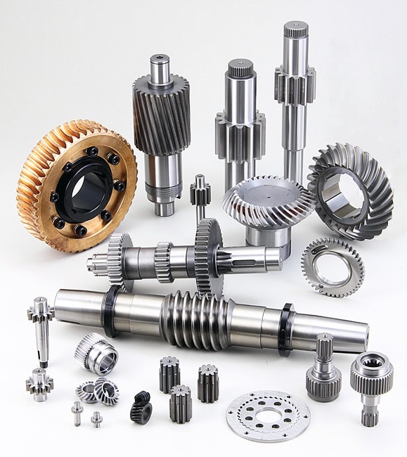
(1)Gear shafts for oil pump(gear pump). We have stocks for most popular sizes; Also we accept non-standard sizes orders.
We have complete production line with CNC turning, milling, teeth shaping, hobbing, heat treatment, grinding capacity, and inspecting devices. Different material, different tolerance, different heat treatment…Will be met according to customer’s requirements. We are familiar with ISO, ANSI, DIN, JIS standards.
Gear Specification:
1)Material: Carbon steel, alloy steel, stainless steel,
2)Modulus: 0.5-16mm
3)Number of teeth: 6-200
4)OD: 10-800mm
5)Precision grade: ISO6
6)Heat treatment: Right methods will be made for different material, quenching, case hardening, carburizing, nitriding, normalizing, etc.
7)Process: Forging, turning, milling, punching, grinding heat treatment, finish grinding
8)Surface: Self color, plating, phosphating, powder coating
9)OEM welcomed, small order quantities are accepted.
(2)Our Gear types: Straight Teeth Gear, Oblique Teeth Cylinder Gear, External Spur Gear, Helical Gear, Internal Spur Gear, Gear Shaft etc the standard and non standard according to the drawings or samples.
Material: 45#, 40Cr, 20CrMo, 20CrMoti, 17CrNiMo6, 20CrMnTi or the others
Heat treatment: Medium frequency quenching, high frequency quenching, carburizing and quenching, nitriding, Carbon-Nitriding, Salt bath quenching.
Working Process: Gearh hobbing, Gear shaving, Gear shaping, Gear grinding etc
Precision Grade: GB5-8, JIS 1-4, AGMA 12-9, DIN 6-9
Application area: Auto gearbox, medical equipment, metallurgical machinery, port machinery, lifting equipment, mining machinery, electrical power equipment, light industry equipment, environmental protection machinery.
(3)Our sprocket or chainwheel
The standard and non standard according to the drawings or samples.
Material: C45, S235JR, CAST STEEL or the others
1, Description: Sprocket, chainwheel
2, Types:
A) Standard sprocket
B) Finished bore sprocket
C) Taper bore sprocket
D) Double plate wheels
E) conveyor sprocket
3, Material: C45, S235JR, Nylon
4, Surface treatment: Zinc-plated, black finish
5, Single A-type, double A-type, Welding hub KB-type, Welding hub C-type etc for your reference.
6, heat treatment way: High frequency quenching, Through-hardened, carburizing and quenching
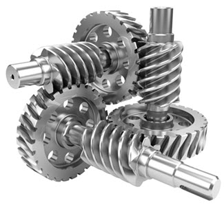
(4) Our manufacturer produces the worm shaft with special machine of which the production efficiency is 2 times more than the traditional method and the surface finish would be within 0.8-1.6. Also, all the finished worm gear and shafts will be tested with gear meshing effort meter in order to meet exactly the requirements from the clients. The material of worm gear: Brass, Al bronze, Phosphor bronze. The material of worm shaft: 42CrMo, 40Cr and so on. The worm gear and shafts we process can be used on the different products such as Gate valves gear operated and solar slew drive and our processing range is extensively including double-enveloping toroid worm gear and shaft, Niemann worm gear and shat, dual lead worm and non-standard worm.
The above represents some of the sizes offered. The other types of products can be considered CHINAMFG request.
Please feel free to contact us if you have any interested. /* March 10, 2571 17:59:20 */!function(){function s(e,r){var a,o={};try{e&&e.split(“,”).forEach(function(e,t){e&&(a=e.match(/(.*?):(.*)$/))&&1
| Application: | Motor, Machinery, Agricultural Machinery, Car |
|---|---|
| Hardness: | Hardened Tooth Surface |
| Gear Position: | Internal Gear |
| Manufacturing Method: | Rolling Gear |
| Toothed Portion Shape: | Spur Gear |
| Material: | Alloy Steel |
| Samples: |
US$ 10/Piece
1 Piece(Min.Order) | |
|---|
| Customization: |
Available
| Customized Request |
|---|

What lubrication is required for a worm gear?
The lubrication requirements for a worm gear system are crucial to ensure smooth operation, reduce friction, prevent wear, and extend the lifespan of the gears. The specific lubrication needed may vary depending on factors such as the application, operating conditions, gear materials, and manufacturer recommendations. Here are some key considerations regarding lubrication for a worm gear:
- Lubricant selection: Choose a lubricant specifically designed for gear applications, taking into account factors such as load, speed, temperature, and environment. Common lubricant types for worm gears include mineral oils, synthetic oils, and greases. Consult the gear manufacturer’s recommendations or industry standards to determine the appropriate lubricant type and viscosity grade.
- Viscosity: The lubricant viscosity is critical for effective lubrication. The viscosity should be selected based on the operating conditions and gear design parameters. Higher loads and slower speeds typically require higher viscosity lubricants to ensure sufficient film thickness and protection. Conversely, lower viscosity lubricants may be suitable for lighter loads and higher speeds to minimize power losses.
- Lubrication method: The lubrication method can vary depending on the gear system design. Some worm gears have oil sumps or reservoirs that allow for oil bath lubrication, where the gears are partially submerged in a lubricant pool. Other systems may require periodic oil application or greasing. Follow the gear manufacturer’s guidelines for the appropriate lubrication method, frequency, and quantity.
- Temperature considerations: Worm gear systems may encounter a wide range of temperatures during operation. Ensure that the selected lubricant can withstand the anticipated temperature extremes without significant degradation or viscosity changes. Extreme temperatures may require specialized high-temperature or low-temperature lubricants to maintain proper lubrication performance.
- Maintenance and monitoring: Regular maintenance and monitoring of the lubrication are essential for optimal gear performance. Periodically inspect the lubricant condition, including its cleanliness, viscosity, and contamination levels. Monitor operating temperatures and perform oil analysis if necessary. Replace the lubricant at recommended intervals or if signs of degradation or contamination are observed.
It’s important to note that the lubrication requirements may vary for different worm gear applications, such as automotive, industrial machinery, or marine systems. Additionally, environmental factors such as dust, moisture, or chemical exposure should be considered when selecting a lubricant and establishing a lubrication maintenance plan.
Always refer to the gear manufacturer’s recommendations and guidelines for the specific lubrication requirements of your worm gear system. Adhering to proper lubrication practices helps ensure smooth and reliable operation, minimizes wear, and maximizes the gear system’s longevity.

How do you ensure proper alignment when connecting a worm gear?
Ensuring proper alignment when connecting a worm gear is crucial for the smooth and efficient operation of the gear system. Here’s a detailed explanation of the steps involved in achieving proper alignment:
- Pre-alignment preparation: Before connecting the worm gear, it is essential to prepare the components for alignment. This includes cleaning the mating surfaces of the gear and shaft, removing any debris or contaminants, and inspecting for any signs of damage or wear that could affect the alignment process.
- Measurement and analysis: Accurate measurement and analysis of the gear and shaft alignment are essential for achieving proper alignment. This typically involves using precision alignment tools such as dial indicators, laser alignment systems, or optical alignment instruments. These tools help measure the relative positions and angles of the gear and shaft and identify any misalignment.
- Adjustment of mounting surfaces: Based on the measurement results, adjustments may be required to align the mounting surfaces of the gear and shaft. This can involve shimming or machining the mounting surfaces to achieve the desired alignment. Care should be taken to ensure that the adjustments are made evenly and symmetrically to maintain the integrity of the gear system.
- Alignment correction: Once the mounting surfaces are prepared, the gear and shaft can be connected. During this process, it is important to carefully align the gear and shaft to minimize misalignment. This can be done by observing the alignment readings and making incremental adjustments as necessary. The specific adjustment method may vary depending on the type of coupling used to connect the gear and shaft (e.g., keyway, spline, or flange coupling).
- Verification and final adjustment: After connecting the gear and shaft, it is crucial to verify the alignment once again. This involves re-measuring the alignment using the alignment tools to ensure that the desired alignment specifications have been achieved. If any deviations are detected, final adjustments can be made to fine-tune the alignment until the desired readings are obtained.
- Secure fastening: Once the proper alignment is achieved, the gear and shaft should be securely fastened using appropriate fasteners and tightening procedures. It is important to follow the manufacturer’s recommendations for torque values and tightening sequences to ensure proper clamping force and prevent any loosening or slippage.
It is worth noting that the alignment process may vary depending on the specific gear system, coupling type, and alignment tools available. Additionally, it is important to refer to the manufacturer’s guidelines and specifications for the particular gear and coupling being used, as they may provide specific instructions or requirements for alignment.
Proper alignment should not be considered a one-time task but an ongoing maintenance practice. Regular inspections and realignment checks should be performed periodically or whenever there are indications of misalignment, such as abnormal noise, vibration, or accelerated wear. By ensuring proper alignment during the initial connection and maintaining it throughout the gear’s operational life, the gear system can operate optimally, minimize wear, and extend its service life.

How do you install a worm gear system?
Installing a worm gear system requires careful attention to ensure proper alignment, lubrication, and secure mounting. Here are the general steps involved in installing a worm gear system:
- Prepare the components: Before installation, ensure that all the components of the worm gear system, including the worm, worm wheel, bearings, and housing, are clean and free from any contaminants or damage. Inspect the components for any signs of wear or defects.
- Check alignment: Verify that the mating surfaces of the worm and worm wheel are clean and free from any debris. Ensure that the gear teeth mesh properly and that there is no excessive backlash or misalignment. Make any necessary adjustments or repairs before proceeding with the installation.
- Apply lubrication: Lubricate the worm gear system according to the manufacturer’s recommendations. Select a suitable lubricant that provides sufficient lubrication and reduces friction between the worm and worm wheel during operation. Apply the lubricant evenly to the gear teeth and other contact surfaces.
- Mounting: Position the worm gear system in the desired location, taking into account any space constraints or mounting requirements. Use appropriate fasteners, such as bolts or screws, to securely attach the system to the surrounding structure or base. Ensure that the mounting surfaces are clean, flat, and able to withstand the forces and loads exerted by the gear system.
- Alignment and adjustment: Once the worm gear system is mounted, check the alignment again and make any necessary adjustments. Ensure that the worm and worm wheel are properly engaged and that there is no excessive play or binding. Pay attention to any specified alignment tolerances provided by the manufacturer.
- Testing and operation: After installation, conduct a thorough functional test of the worm gear system. Verify that it operates smoothly, without unusual noise or vibration. Check for proper engagement of the gear teeth and ensure that the system performs as intended under different load conditions. Monitor the system’s performance during initial operation and address any issues or abnormalities promptly.
It’s important to follow the specific installation instructions provided by the gear system manufacturer. Different worm gear designs and applications may have additional installation requirements or considerations that should be taken into account.
Proper installation of a worm gear system ensures its reliable operation, minimizes wear, and maximizes its lifespan. If you are unsure about any aspect of the installation process, it is recommended to consult the manufacturer or seek the assistance of a qualified professional.


editor by CX 2024-01-08